
Guitar Vibrato circuit

The circuit in question is designed to function as a phase shifter, which is a critical component in various electronic applications, including signal processing and communication systems. The operational amplifier (op-amp) configuration used in this circuit typically consists of resistors and capacitors that determine the phase shift characteristics. When implementing this circuit, it is essential to select components that minimize noise and distortion to maintain signal integrity.
The use of Field-Effect Transistors (FETs) in this design is significant due to their high input impedance and low output impedance, which are advantageous for maintaining signal fidelity. However, the matching of FETs is crucial because mismatched devices can lead to phase errors and degrade performance. When utilizing off-the-shelf FETs, careful consideration must be given to their specifications to ensure compatibility with the circuit's requirements.
In terms of the setup process, it may involve adjusting the biasing conditions and feedback components to achieve the desired phase shift. This may require iterative testing and measurement to fine-tune the circuit. The critical parameters to monitor include the gain, phase shift, and linearity of the output signal. It is advisable to use precision variable resistors to allow for fine adjustments during the calibration phase.
Overall, while the circuit's design is straightforward, the challenges associated with component selection and setup necessitate a thorough understanding of the operational principles and characteristics of the devices involved. Proper execution of this circuit can lead to effective phase shifting capabilities, suitable for a variety of electronic applications.The circuit of the unit is fairly simple, but is a bit irksome to set up. The reason is that obtaining matched FETs is not easy, so I had to make sure that the circuit would work with off-the-shelf FETs. The phase shifter is a standard opamp circuit, and has been used for this sort of application many times.
After experimenting with alternative va riable resistors, I decided that the FET was still the best choice, although they are fairly critical to set up, and have linearity problems.
Related Circuits
This sound effects circuit is designed to function as a signal distorter. When utilized with an electric guitar, it enables the creation of unique sound effects. The sound effects circuit operates by manipulating the input audio signal from the electric...
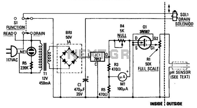
The drain-to-source resistance of Q1 varies depending on the acidity of the sample presented to Q1's gate circuit. This variable resistance influences the current flowing through the bridge, which is proportional to pH. The circuit involves a field-effect transistor (FET),...
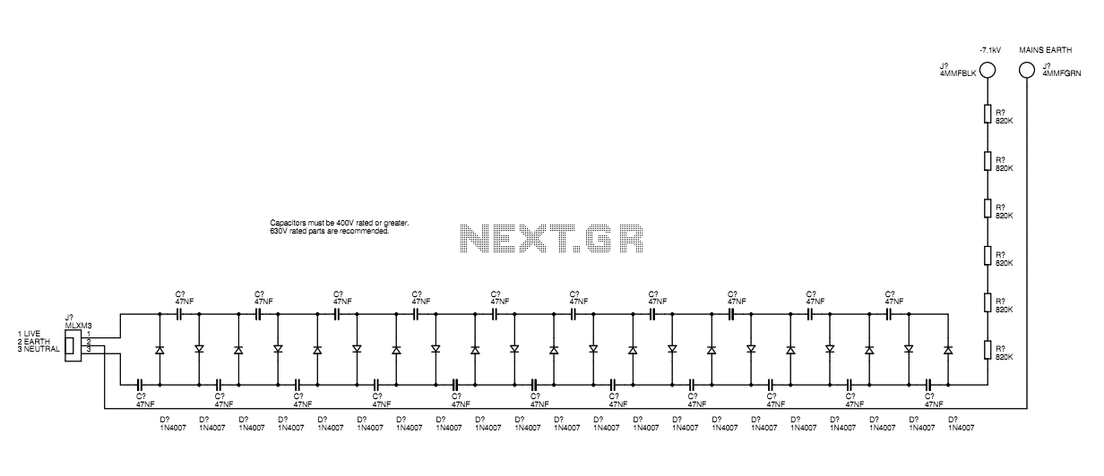
A basic mains driven Cockroft ladder high voltage generator is shown in the schematic. This is functionally the same as a project in Electronics Today International many years ago. The peak mains voltage of 340V appears across each capacitor...
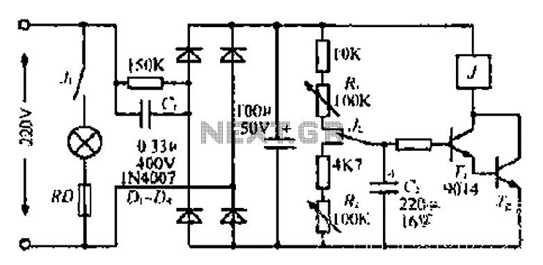
220V mains electricity is sent through a 0.33 µF capacitor (Ci) and a 50 kΩ resistive drop. A bridge rectifier composed of diodes D1 to D4 converts the AC voltage to DC. After passing through a 100 µF capacitor...

This car audio amplifier circuit is based on the LA47536 audio amplifier integrated circuit designed by Sanyo. This audio amplifier circuit is specifically designed for car audio power amplifiers. The LA47536 car audio amplifier IC features four output channels...
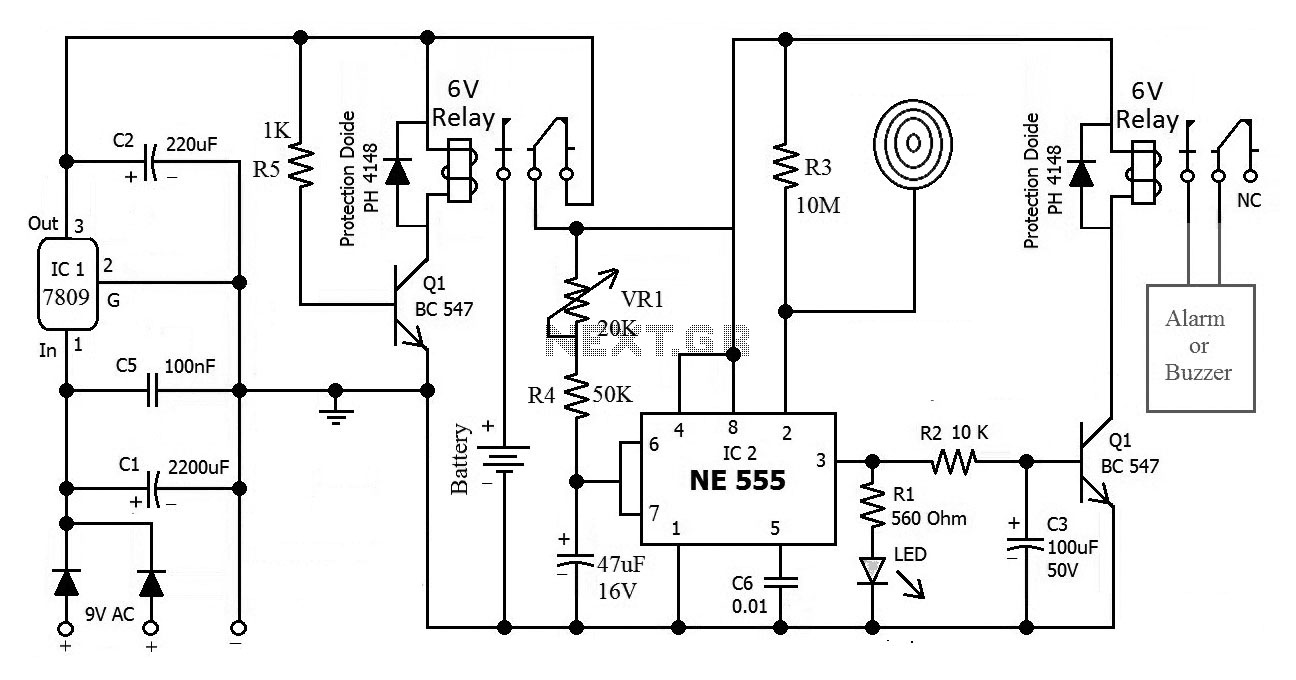
This is the circuit diagram of a touch-activated alarm system that remains operational during power outages. The alarm system is triggered when someone touches the designated touch plate. A notable feature of this circuit is the automatic battery activator,...