
Acid-Rain Monitor Circuit

The circuit involves a field-effect transistor (FET), specifically Q1, whose drain-to-source resistance (R_DS) is affected by the pH level of the sample solution. When the acidity of the sample changes, it alters the gate voltage of Q1, which in turn modifies the resistance. This change in resistance directly affects the current (I) flowing through the bridge circuit, where the bridge is typically configured to measure small changes in voltage that correspond to variations in current.
The bridge circuit may consist of resistors arranged in a Wheatstone bridge configuration, allowing for precise measurements of the current changes. The output voltage from the bridge is then related to the pH level, enabling the circuit to function as a pH sensor.
For optimal performance, it is essential to consider the characteristics of Q1, including its threshold voltage, transconductance, and output conductance, as these parameters will determine the sensitivity and accuracy of the pH measurement. Additionally, the selection of appropriate reference electrodes and calibration techniques will enhance the reliability of the readings obtained from the circuit. The overall design should ensure minimal noise and interference, which can affect the precision of the pH measurement. The drain-to-source resistance of Ql varies depending on the acidity of the sample presented to Ql`s gate circuit. That variable resistance varies the current flowing through the bridge; that current is proportional to pH.
Related Circuits
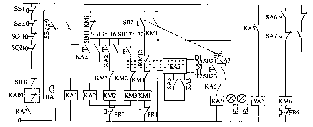
The operation control circuit is primarily managed by the button switch SB21. The contactor KM1, composed of the main contactor KM1, directly controls the operation of the main motor M1. The main motor M1 serves as the prime mover,...
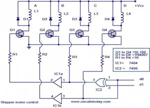
The following circuit illustrates a Stepper Motor Controller Circuit Diagram. This circuit is based on the 7404 IC. Features include a simple stepper motor. The stepper motor controller circuit utilizing the 7404 IC is designed to drive a stepper motor...
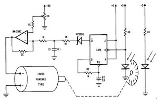
A simple encoder circuit for a DC motor can be constructed using the provided circuit diagram. The system includes the HA-2542 operational amplifier, a small 12 V DC motor, and a position encoder. During operation, the encoder generates a...
The two amplifiers in question share many features, differing primarily in their power sections. This allows for a combined understanding of their characteristics. Auditioning both amplifiers will provide insights into the musical differences between Class A and Class AB...
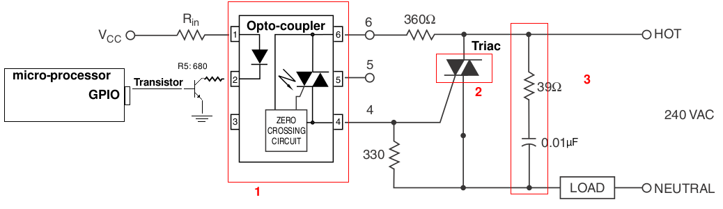
A light-dimming control system is being developed for a 240V heat lamp with a power dissipation of approximately 250W. The objective is to adjust the heat output of the lamp using control from a microprocessor. The development is based...
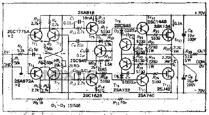
The south circuit consists of four parts, arranged in descending order: an NPN transistor dynamic garbage device (T1), a PNP transistor differential amplifier (T2, T3) forming a double differential circuit, two balanced output amplifiers with opposite phase, and a...