
Conducting pipe control one rechargeable short delay circuit

The circuit utilizes a timing mechanism that allows for the adjustment of delay intervals between 0.5 seconds and 3.5 seconds. This is achieved through the integration of a potentiometer, designated as RP, which serves as a variable resistor. By altering the resistance value through the rotation of the potentiometer, the charge time of a timing capacitor in the circuit can be modified, thereby changing the delay time.
In a typical configuration, the circuit may include a 555 timer IC in monostable mode, where the output pulse width is determined by the equation:
\[ T = 1.1 \times R \times C \]
Here, \( T \) represents the delay time, \( R \) is the resistance (in ohms) set by the potentiometer, and \( C \) is the capacitance (in farads) of the timing capacitor. The choice of capacitor value will influence the maximum and minimum delay times achievable.
To implement this circuit, the following components are typically required:
- A 555 timer IC.
- A potentiometer (RP) for adjusting the delay time.
- A timing capacitor (C) with an appropriate capacitance value.
- Additional passive components such as resistors and diodes may be included for stability and protection.
The output of the circuit can be connected to various devices or indicators, such as LEDs or relays, to visualize or utilize the delayed signal. Proper consideration should be given to the power supply voltage and current ratings of all components to ensure reliable operation.
This circuit design is suitable for applications requiring timed delays, such as in automation systems, timers, or triggering mechanisms.Delay time is 0.5 ~ 3. 5s, adjustment potentiometer RP, can change the delay time.
Related Circuits
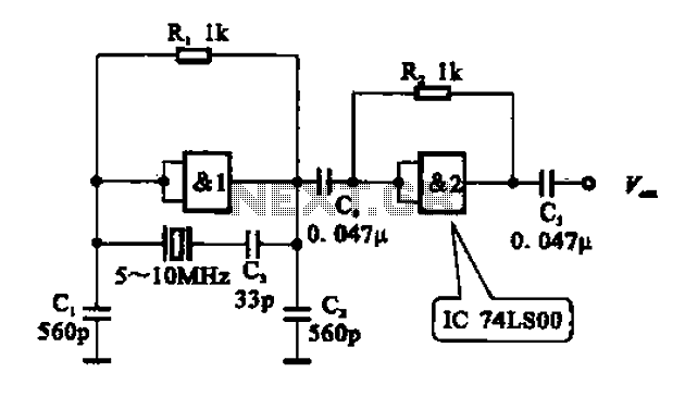
A crystal oscillator circuit comprises various gates as illustrated in the provided figures. Figure (A) represents a crystal oscillator circuit operating at 1 MHz, while figure (B) depicts a 20 MHz crystal oscillator circuit. Figure (C) shows a variable...
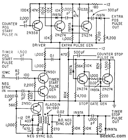
The timer start-pulse generator is a fast series-transistor coincidence circuit. The slope-gate generator is a one-shot multivibrator that prevents the 1N97A diode from passing the blocking oscillator's negative sync pulse until the multivibrator fires. This circuit is utilized to...
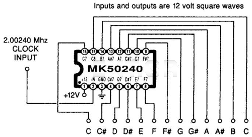
Using an MK50240, this circuit generates 12 top octave tones. The input and output lines can be separated using a binary divider IC to achieve the lower notes. Inputs and outputs are 12-volt square waves. The MK50240 is a specialized...
After conducting experiments with a rotary encoder connected directly to keyboard switches, it was found that the keyboard controller IC (an Intel P8049AH in this case) is unable to detect pulses that are too narrow. Testing involved rotating the...
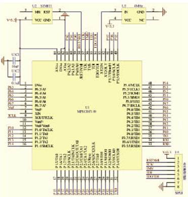
The target designator is designed based on the MSP430F149 microcontroller to facilitate rapid target identification in military training environments. It can adapt to various tactical requirements, allowing for the display of targets and the execution of bomb simulations according...
Capacitor discharge firing boxes are suitable for specific types of electric match ignition but not for others. Experimenting with this technology can be enjoyable and educational; however, the expense of a commercial capacitor discharge (CD) firing box can be...