
H-Bridge

MOS transistors are generally preferred in H-bridge applications due to their lower voltage drop, which corresponds to the residual resistance when saturated (RDS(on)) multiplied by the load current. The resistance values for RDS(on) are relatively low, thus minimizing power dissipation. Similar to bipolar transistors, P-channel MOSFETs are used for the upper switches and N-channel MOSFETs for the lower switches. When controlling inductive loads, such as motors, it is important to manage voltage spikes that can occur when the voltage across the load is reversed, as these spikes can damage the switches. A common solution is to place diodes across the switches to provide protection. It is essential that the diode protection activates quickly during switching, which is why Schottky diodes are often chosen due to their low forward voltage drop (approximately 0.3 volts) and rapid recovery time (Trr as specified in datasheets).
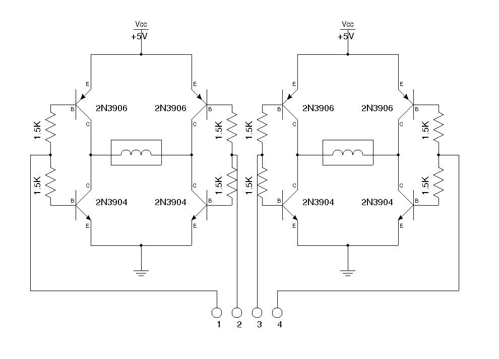
To prevent simultaneous activation of switches in the same branch, which could lead to a short circuit between the load power and the ground, a control mechanism is implemented that ensures only one switch in a branch is on at any given time. This is typically achieved through joint control of transistors in the same branch with an inverter placed between each switch. Additionally, resistors limiting the current to the base of the bridge (R1 to R4) can be included to manage heat dissipation and facilitate external control of the current flowing through the bridge during switching events. NPN transistors are also employed to interface between the electronic control unit (often operating at TTL levels) and the power supply of the bridge, which is often decoupled from the control electronics to prevent the transmission of switching noise from the load.
The NPN transistor circuit is designed to prevent the simultaneous activation of both switches in the same branch by exploiting the characteristics of the P-channel and N-channel transistors. To vary the motor's speed, the current through the motor must be adjusted, typically using a PWM (Pulse Width Modulation) control technique. This method allows for fine control of the motor speed by adjusting the duty cycle of the PWM signal, thereby controlling the average voltage and current supplied to the motor.To drive a DC motor, we need to reverse the voltage across it to control the direction of rotation. To do this, we use what is called an H-bridge. The H-bridge consists of two branches on which we connect the two terminals of the motor. Each branch is composed of two alternately controlled switches. In the diagram above, one can imagine the path taken by the current to the motor (connected to terminals M1 and M2). The first path is formed by switching off the switches U$4 and U$2 and turning on the switches U$3 and U$1. To reverse the current and thus reverse the direction of rotation, it opens the switches U$4 and U$2 and closes the switches U$3 and U$1 (the order of opening / closing is important to avoid short-circuit.
). Bipolar transistors: we can use bipolar transistors as switches. It generally uses PNP transistors for switches on the top (1 and 2) and NPN transistors for both bottom switches (3 and 4). One problem often encountered when using bipolar transistors for the H-bridges, is the power dissipated by these transistors.
Indeed, each transistor has a voltage drop at its terminals even when saturated (residual voltage between the collector and emitter of transistor saturation: VCEsat). This in line voltage drop multiplied by the current through the load corresponds to a power dissipated in the transistor; limiting the current in the load, but also does not allow to apply the full supply voltage to the load.
The voltage applied to the load is the supply voltage minus 2 X VCEsat. MOS: MOS transistors are better suited to be used in H-bridge. Indeed, their voltage drop is lower and corresponds to the residual resistance when saturated (RDSOn) multiplied by the current load. The resistor in question (Rdson) are quite low and therefore limits the power dissipation. As with bipolar transistors, P-channel MOSFET transistors are used on top and N channel MOSFET transistors at the bottom.
When the load is inductive (motor control for example), make sure that when the voltage across it is reversed, the voltage spikes are reduced to avoid the destruction of the switches. A common solution to this porblem is to place diode across the switches. We must ensure that the protection supplied by the diode is set up as quickly as possible when switching.
Therefore, we choose usually a Schottky diode which has the characteristics of having a low threshold junction (0. 3 volts) and a short recovery time (Trr in the datasheets). Another precaution taken to avoid destroying the bridge is to arrange that the switches of one branch are never switched on simultaneously.
If this happens, a short circuit occurs between the load power and the mass of the bridge destroying it by a very high short circuit current (even higher if the bridge supply comes from a battery). To avoid this, it is arranged to always have a joint command between the transistors of the same branch with an inverter between each switch.
Another solution is to insert a resistor limiting the current in the base of the bridge (resistors R1 to R4 in the diagram above). Please note, however, the heat dissipation. These resistances also allows for a system outside the bridge, to control the current passing through the bridge during each switching.
NPN transistors used to control the bridge are also used to adapt the voltage levels between the electronic control unit (often at TTL level) and the power supply of the bridge itself (often bridge and power control electronics power supplies are decoupled to avoid transmitting the switching noise of the load). The circuit based on NPN transistor is also made to avoid turning on both switches from the same branch of the bridge simultaneously by simply playing on the characteristics of transistors of a single branch (P-channel and N channel).
To be able to vary the speed of rotation, we need to adjust the current through the motor. To do this, use a command type PWM (Pulse W 🔗 External reference
Related Circuits

A design for an H-Bridge has been created to control a 12VDC, 6 Amp motor. The circuit functioned effectively on a breadboard at 7.2 VDC while operating a small DC motor. The H-Bridge circuit is a crucial component in motor...
I decided to make a commercial surface mount PC board using the LED2 sensor concept. It is quite sensitive and can track to a few degrees of accuracy in bright sunlight. If a blocking shadow is used the accuracy...
These circuits could be used as the basis for Model Railroad DCC Boosters or PWM motor controllers. The first schematic is for a basic 3 Amp - DCC Booster using the LMD 18200 CMOS, H-Bridge. Included in the design...
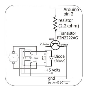
To control the motor, an H-bridge will be utilized in conjunction with a double-pole double-throw (DPDT) relay, as illustrated in the schematic below. For further details, additional resources are available. The proposed circuit employs an H-bridge configuration to facilitate bidirectional...
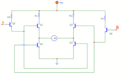
The transistors Q1, Q2, Q3, and Q4 form a bridge circuit. These are typically power transistors designed to handle high current. Transistors Q5 and Q6 drive the bridge. When input A is set high and input B is set...
An H-bridge is commonly utilized for controlling DC motors and stepper motors. When managing a bipolar stepper motor, two complete H-bridges are required. Numerous H-bridge integrated circuits (ICs) such as the L298, MPC17529, and SN754410 (a quad half H-bridge)...