
H-bridge circuit using NPN transistors

The described circuit utilizes a H-bridge configuration, which is commonly employed in motor control applications. The four transistors (Q1, Q2, Q3, Q4) are arranged in a manner that allows for bidirectional control of the motor. Power transistors are selected for their ability to handle significant current loads, ensuring reliable operation under various conditions.
Transistors Q5 and Q6 act as control switches for the H-bridge. By manipulating the states of inputs A and B, the circuit can effectively control the direction of the motor. When A is high and B is low, Q5 conducts, enabling Q1 and Q4, which completes the circuit path, allowing current to flow through the motor in one direction. This configuration is essential for applications requiring forward motion.
In contrast, when A is low and B is high, Q6 turns on, enabling Q3 and Q2. This configuration reverses the current flow through the motor, allowing it to rotate in the opposite direction. This dual control mechanism provides an efficient means of motor direction control, which is crucial for robotics, automation, and various electromechanical systems.
To ensure safe and efficient operation, it is important to consider the specifications of the transistors, including their voltage and current ratings, as well as the thermal management of the circuit. Proper heat sinks may be required to dissipate heat generated during operation, especially under high load conditions. Additionally, incorporating flyback diodes across the motor terminals can protect the transistors from voltage spikes caused by inductive loads, further enhancing the reliability of the circuit.The transistors Q1, Q2, Q3 and Q4 form the bridge circuit. Generally these are power transistors capable of handling high current. Q5 and Q6 drive the bridge. when the `A` is made high and `B` low, transistor Q5 is on and it makes Q1 and Q4 on. The current flows from vcc to ground through Q1, motor and Q4. hence the motor rotates in forward direction. When `A` is made low and `B` high the transistor Q6 is on and it makes the Q3 and Q2 on. The current flow from vcc to ground through Q3, motor and Q2. hence the motor rotates in reverse direction. 🔗 External reference
Related Circuits
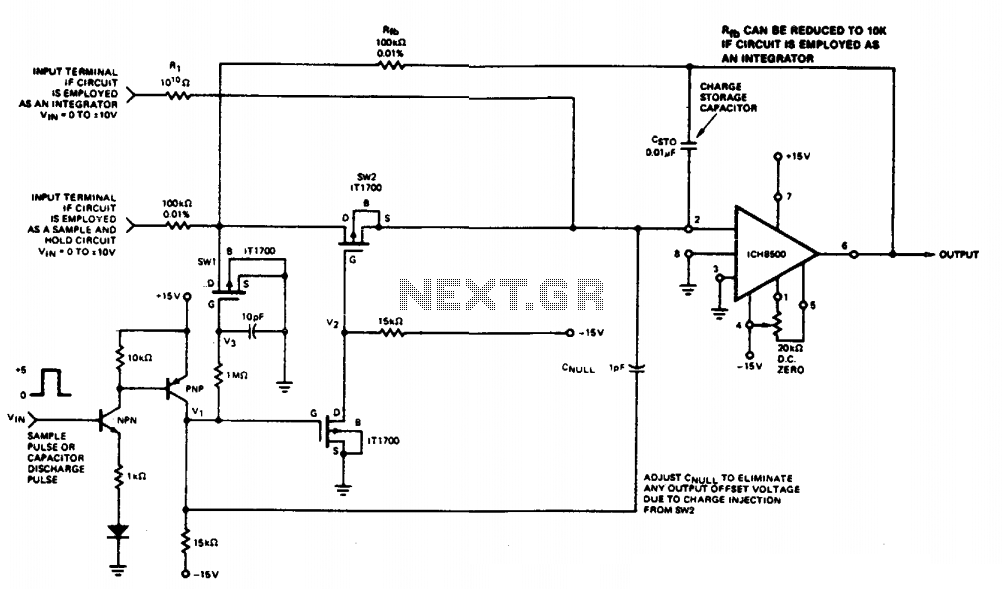
This circuit quickly charges capacitor CST0 to a voltage that matches an input signal. After charging, the input signal is electrically disconnected from the capacitor, allowing the charge to remain on CST0. Since CST0 is part of the negative...
An electrical circuit that ensures when two or more generators are connected in parallel to a power system, they share the load equally. In this arrangement, if the voltage of one generator is slightly higher than that of the...
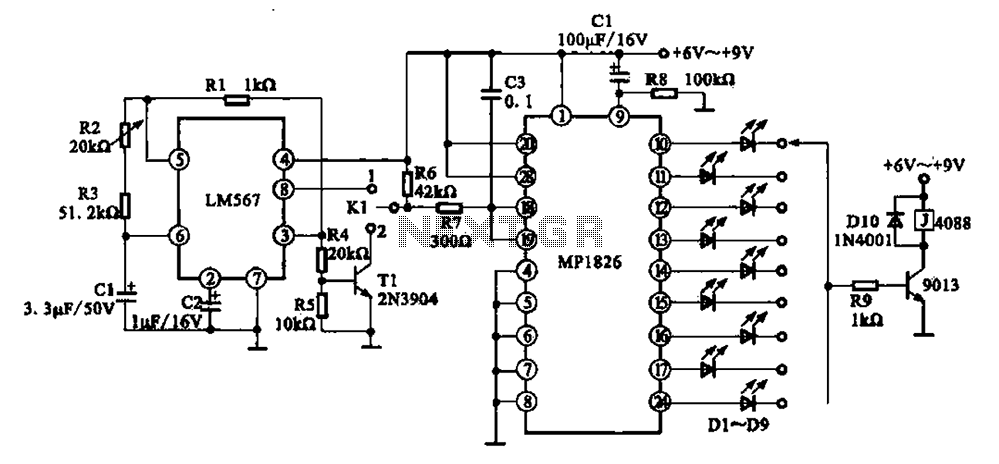
A precision circuit utilizing the LM567 timer, specifically the MPI826, where the LM567 functions as a dual-band oscillator. The MP1826 serves as a divider in the circuit, allowing the output signal from the LM567 to achieve extended timing. The...
This document outlines a basic circuit designed to power high impedance, high voltage, low current devices such as electroluminescent (EL) backlights and fluorescent tubes. The project originated from the need for a simple yet flexible inverter circuit for an...
The 555 timer is utilized as a clock source to drive the RS7490 decimal counter, providing a BCD output to a 7-segment LED display. The clock frequency can be adjusted by changing the value of resistor R1. The circuit operates...
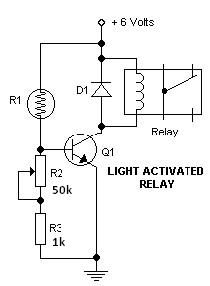
This light-dark switch activated relay circuit schematic represents one of the simplest electronic circuits designed to activate other electronic devices based on light or darkness. It requires a single electronic relay and a few common components that are not...