
H-bridge using only n-channel mosfets

The H-bridge configuration is a crucial component in various applications, particularly in controlling the direction of a DC motor. The use of four floating gate drivers allows for efficient control of the IGBTs, which are known for their high efficiency and fast switching capabilities. Each IGBT is responsible for switching the current in the motor, enabling bidirectional control.
In the provided schematic, the floating gate drivers are connected to the gates of the IGBTs, ensuring that the transistors can be turned on and off with precision. The floating gate drivers are instrumental in providing the necessary voltage levels to fully enhance the IGBTs, thereby minimizing switching losses and improving overall performance.
The H-bridge operates by alternately switching pairs of IGBTs on and off. For instance, when the upper left and lower right IGBTs are activated, current flows in one direction, causing the motor to rotate in a specific direction. Conversely, activating the upper right and lower left IGBTs reverses the current flow, allowing for reverse rotation of the motor.
Design considerations for this H-bridge circuit include ensuring proper gate drive voltage levels, managing heat dissipation from the IGBTs, and implementing protection mechanisms such as overcurrent and overvoltage protection. Additionally, the layout of the PCB should minimize parasitic inductance and capacitance to enhance performance and reliability.
In summary, this H-bridge configuration, featuring floating gate drivers and IGBTs, is a robust solution for motor control applications, offering efficient operation and flexibility in direction control. Further refinements may enhance its performance and reliability in practical implementations.I have created an H-bridge PC with 4x floating gate drivers and 4x IGBTs (see attached schematic showing half of h-bridge). It works very nicely but I .. 🔗 External reference
Related Circuits

Introduction It is time for the 8-pin microcontroller Microchip PIC12C508, the SAVER V3.2, a new design of a device that controls a night light by turning it on and off. The SAVER V3.2 utilizes the Microchip PIC12C508 microcontroller, which features...

This is a simple siren sound generator with high power output and significant noise. The circuit utilizes digital ICs, specifically the CD4046, in an inverter configuration, along with four transistors to amplify the current output to a horn speaker...

A simple metal detector electronic project circuit can be designed using the CS209A integrated circuit manufactured by Cherry Semiconductor. The CS209A integrated circuit is a bipolar monolithic integrated circuit intended for metal detection and proximity sensing applications. It incorporates...

The 4000 Series 4011B is a NAND gate used in conjunction with a 4AI NAND gate circuit group to create two loops of an unstable multivibrator. The first NAND gate and the second NAND gate operate at approximately 1...
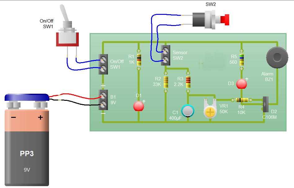
When the sensor switch SW2 is pressed, the LED D3 and the alarm are activated for a certain duration. The timing of the circuit is determined by the resistor R3 and capacitor C1. Additional details regarding the RC circuit...
Government data sets available online are often sourced from major metropolitan areas or infrastructural centers. With an easy-to-follow introduction to new software and technologies, the urban sensor kit allows anyone to obtain location-specific information and share it with a...