
Half-wave rectifier

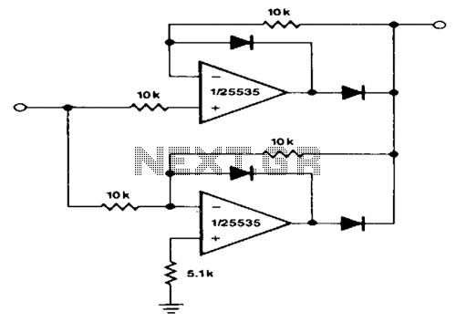
The half-wave rectifier circuit described utilizes two diodes arranged in such a way that they allow current to flow in one direction while blocking it in the opposite direction. The operational amplifier, NE5535, is employed to enhance the performance of the rectifier, ensuring that the output signal is amplified as per the defined gain characteristics. The gain of 0 for positive signals indicates that these signals will not pass through the circuit, while negative signals will be inverted and amplified by a factor of -1, resulting in a mirrored output.
In applications where the output impedance is a concern, additional buffering stages may be implemented. This could involve the use of a voltage follower configuration, which utilizes an operational amplifier to provide a high input impedance and a low output impedance, effectively isolating the rectifier circuit from the load. This buffering ensures that the load does not affect the performance of the rectifier, particularly when dealing with varying input signal characteristics.
The necessity for the output to slew through two diode drops is a critical consideration, as it impacts the response time of the circuit when the input polarity changes. This characteristic is particularly relevant in high-frequency applications, where rapid signal changes are common. The NE5535's capability to operate effectively at frequencies up to 10 kHz with minimal distortion makes it suitable for a range of audio and signal processing applications, where fidelity and accuracy are paramount.
In summary, this half-wave rectification circuit is designed to provide precise signal processing with specific gain characteristics and considerations for output impedance and frequency response, making it a valuable component in various electronic applications.This circuit provides for accurate half wave rectification of the incoming signal. For positive signals, the gain is 0; for negative signals, the gain is — 1. By reversing both diodes, the polarity can be inverted. This circuit provides an accurate output, but the output impedance differs for the two input polarities and buffering may be needed The output must slew through two diode drops when the input polarity reverses. The NE5535 device will work up to 10 kHz with less ttan 5% distortion.
Related Circuits
A precision half-wave rectifier utilizing an operational amplifier will achieve a rectification accuracy of 1% from DC to 100 kHz. A precision half-wave rectifier circuit is designed to convert an AC signal into a unidirectional output while maintaining high accuracy...
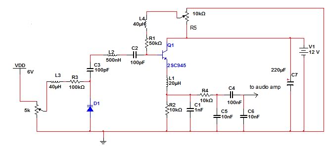
The circuit described is an FM receiver. When a 9V power supply is used, the circuit exhibits good performance. However, performance issues arise when an AC/DC rectifier or switch-mode power supply is utilized. The FM receiver circuit operates by demodulating...
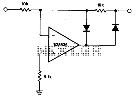
The circuit enables precise half-wave rectification of the incoming signal. It exhibits a gain of 0 for positive signals and a gain of -1 for negative signals. By reversing both diodes, the polarity can be inverted. While this circuit...
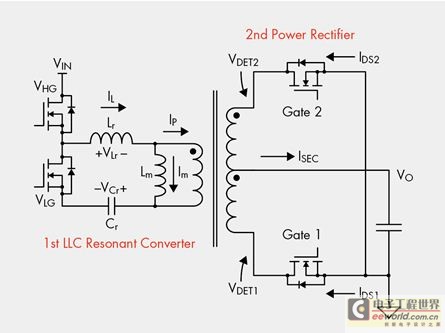
The designer is looking for a solution with higher efficiency and lower power consumption in order to minimize unnecessary energy loss. The approach involves using syntony inductance to harmonize the capacitive LLC syntony converter, employing zero voltage switching (ZVS)...
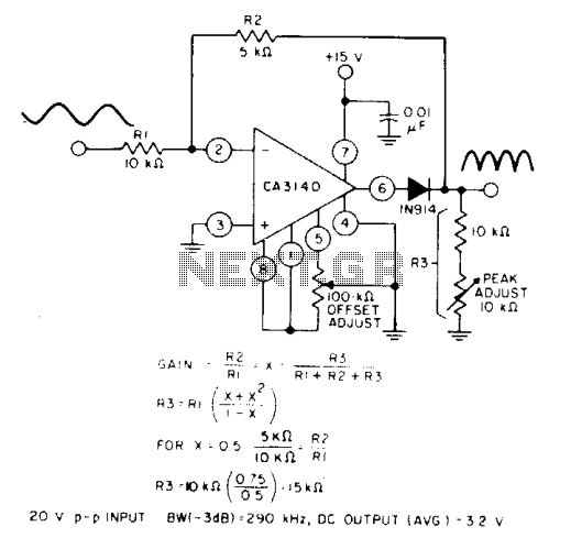
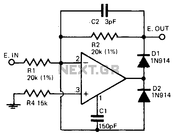
When the equality of two equations is satisfied, the full-wave output of the circuit is symmetrical. The circuit utilizes a CA3140 BiMOS operational amplifier in an inverting gain configuration. The circuit design featuring the CA3140 BiMOS operational amplifier is characterized...
This circuit provides accurate full-wave rectification. The output impedance is low for both input polarities, and the errors are small at all signal levels. It is important to note that the output will not sink heavy currents, except for...