
Promote the power of synchronous rectifier of secondary end in the syntony converter of the semi-bridge

The LLC syntony converter's architecture is characterized by its ability to operate efficiently across various load conditions, particularly in high-frequency applications. The integration of zero voltage switching (ZVS) significantly reduces switching losses, enhancing overall efficiency. The design employs a resonant tank circuit, which consists of inductors and capacitors that resonate at a specific frequency, allowing for soft switching conditions. This minimizes stress on the MOSFETs, prolonging their lifespan and improving reliability.
In the synchronous rectifier circuit, the control mechanisms for the MOSFETs are crucial. The use of feedback loops from the secondary current allows for precise timing adjustments, ensuring that the MOSFETs switch in sync with the resonant waveform. This synchronous operation mitigates the reverse recovery losses typically seen in diodes, further enhancing efficiency.
The current transformers play a pivotal role in monitoring the secondary current. By converting the current to a manageable voltage signal, they provide the necessary feedback for the control circuitry. The design should ensure that the current transformers are appropriately rated to handle the expected peak currents, while also maintaining a high degree of accuracy in the signal transformation.
The PCB layout must be carefully considered to minimize parasitic inductance and capacitance, which could adversely affect performance. The placement of components should facilitate efficient routing of power and signal paths, while also considering thermal management to dissipate heat generated by the MOSFETs during operation.
In summary, the implementation of an LLC syntony converter with synchronous rectification and advanced control techniques presents a promising solution for achieving high efficiency and low power consumption in power electronics applications. By leveraging the unique characteristics of the LLC topology and optimizing the control of MOSFETs, designers can significantly reduce energy losses and enhance system performance.The designer is seeking the solution with higher efficiency, with lower power consumption, in the hope of reducing the needless energy loss. Utilize syntony inductance to shake the capacitive LLC syntony converter harmoniously, use the zero voltage switch ZVS Or a current switch ZCS Can obtain more efficient solution.
Though LLC syntony converter has more high efficiency, adopt the discontinuous mode DCM Or the mode BCM that the borderline is turned on The electric current of the secondary end MOSFET of the work may cause the power consumption. This text will discuss how to use the second order to carry the synchronous rectifier circuit to reduce the power consumption, canvass the control method of using the electric current of secondary end to make MOSFET turned on and shut off synchronously, and control the voltage of MOSFET and method of time of the feed-through with LLC primary-side grid signal.
In order to obtain more high efficiency, compare with 200W to the positive excited converter of 800W two-hose sharing, the primary-side MOSFET of LLC syntony converter can reach the zero voltage switch ZVS easily, In the hope of saving energy, and obtain more high efficiency. In addition, LLC syntony converter uses the unique part, can omit the stored energy inductance of the secondary end, superior to the scheme of the positive excited converter of two-hose sharing, and reduce the area of position occupied on the p-c board.
Because of the characteristic of LLC syntony converter, will turn on the mode BCM with the borderline Or discontinuous mode DCM Deal with the electric current of secondary end, the electric current crest value will be greater than the crest value of electric current of the positive excited converter of two-hose sharing. Will introduce several kinds and control the method that MOSFET will be turned on and shut off with different testing signals as follows.
When LLC syntony converter controls the secondary end rectifier, especially while shut off, the control timing that MOSFET turns on and shuts off is very important. We can use and measure LLC syntony converter primary-side or electric current of the secondary end or way of the voltage signal, come to the area that confirm MOSFET turn on.
Fig. 1 is the synchronous rectification circuit diagram of LLC converter. We use voltage and electric current symbol as shown, introduce four kinds of methods to control MOSFET while the secondary end synchronous rectifier shut off. Through measuring the electric current of MOSFET, the time that can make use of secondary end synchronous rectifier to control MOSFET to be turned on and shut off, as shown in Fig.
2 and 3. Because need to measure IDS1 and IDS2, need to increase a current transformer Current Transformer, CT, Obtain the control information from MOSFET signal. Compared with electric current of primary-side, the electric current of secondary end should be a bit bigger, so the ratio of winding of the current transformer is very large.
Finally, designers can use the electric current signal transformation voltage signal that the resistance will be separated, and send it to the logical circuit to control MOSFET device. Fig. 2 shows in order to measure the electric current signal, the situation as measuring the electric current signal of Fig.
3 with a current transformer shown with two current transformers, in this design, the circuit overall arrangement receives more restrictions, but saved a current transformer and saved the breadboard area. Fig. 4 shows for the situation of each phase place, this phase place uses the voltage changed by the detection electric current of the current transformer, in order to control MOSFET waveform and GATE signal.
The level presumed is used as the guiding mark that 🔗 External reference
Related Circuits
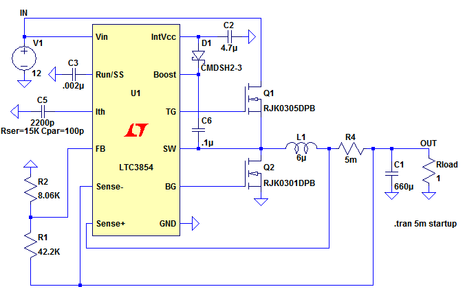
The top MOSFET activates, creating a short circuit between the input voltage (IN) and the left side of the inductor, L1. The inductor current increases according to the equation where V is the voltage across the inductor, L is...
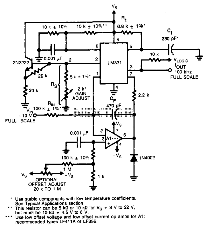
This circuit utilizes a conventional operational amplifier in conjunction with a feedback capacitor (CF) to perform integration. When the output of the integrator exceeds the nominal threshold level at pin 6 of the LM131, it triggers the timing cycle....
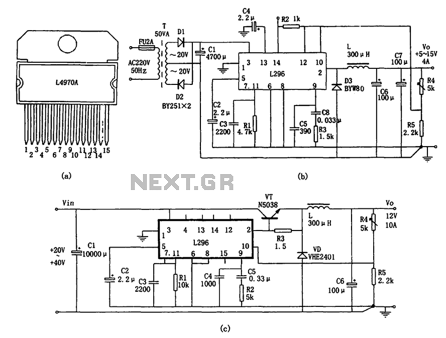
The L296 chip is a high-current switching power supply component designed to operate within a voltage range of 5 to 15V and provide an output current of up to 4A. This monolithic chip incorporates several features including enhanced protection...
Features: 1.3-12.2 V, 1 A, over-current protection. This is a simple but reliable device based one of the oldest integrated voltage regulators of them all - the LM723. The LM723 voltage regulator is a versatile and widely used component in...
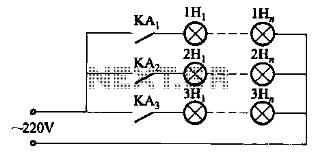
The relay control system utilizes multiple pairs of contacts, allowing for the connection of higher power lamps in parallel. The circuit design is straightforward; by altering the capacitance of the capacitor, different flashing frequencies can be achieved. The described circuit...
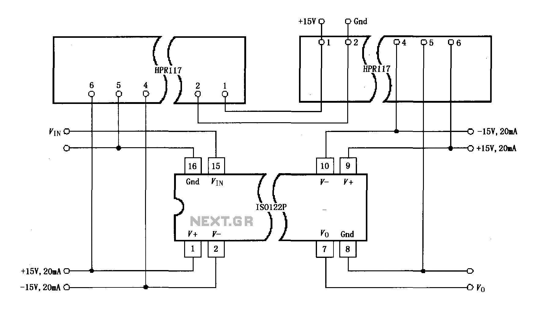
Power isolation is demonstrated for the ISO122P / 124, which features a three-port amplifier. The circuit also utilizes precision analog isolation amplifiers. The ISO122P / 124 isolation amplifier is a cost-effective solution, and the HPR117 DC/DC converter component provides...