
Help me fix the noise in a FM receiver with AC/DC rectifier

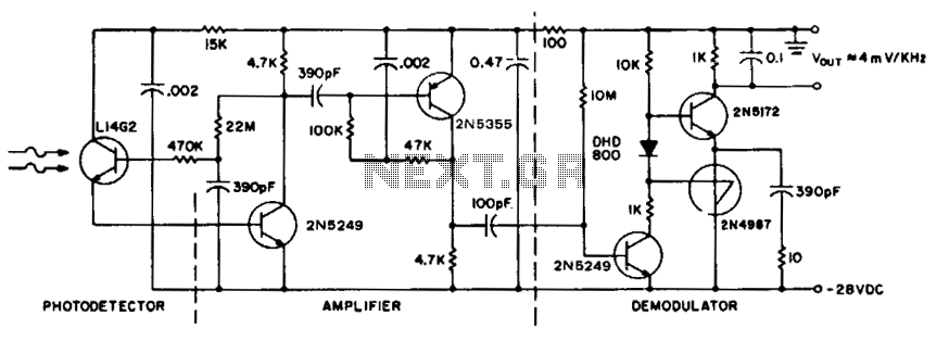
The FM receiver circuit operates by demodulating frequency-modulated signals to retrieve the original audio signal. The circuit typically consists of several key components: an antenna for signal reception, a radio frequency (RF) amplifier to boost the received signal, a mixer to convert the RF signal to an intermediate frequency (IF), and a demodulator to extract the audio information from the IF signal.
In this particular design, a 9V power supply is optimal, as it provides adequate voltage for the RF amplifier and other active components, ensuring stable performance and sufficient gain. The use of an AC/DC rectifier or a switch-mode power supply may introduce noise or ripple voltage that can adversely affect the sensitive components of the circuit, leading to degraded audio quality or loss of signal.
To enhance the performance of the FM receiver, it is advisable to include bypass capacitors near the power supply pins of the active components. This will help filter out high-frequency noise and stabilize the voltage supply. Additionally, careful layout considerations should be made to minimize interference, such as keeping the RF and audio sections physically separated and using shielded cables for the antenna.
Overall, the FM receiver circuit's performance is highly dependent on the quality of the power supply and the proper design of the circuit layout.The above circuit is fm receiver. when i used pin supply 9V, this circuit had quite nice performence. But when i used AC/DC rectifier or switch supply .. 🔗 External reference
Related Circuits
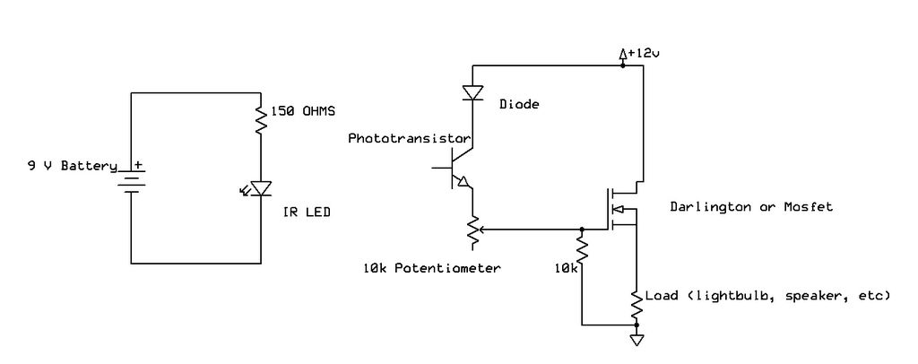
Recently, samples of IR LEDs and a corresponding IR phototransistor were acquired. A project was initiated to utilize these components. The project involves the integration of infrared (IR) LEDs with an IR phototransistor to create a simple optical communication system...
The diagram illustrates the principle circuit of a radio control car receiver. Important notes include the selection of transistor Q1, which is specified as either 1815 or 9018, along with the bias resistor R1, which has values of 240K...
The game was originally designed to position three balls locked in holes on a slowly rotating ring around the Deadworld. Once the third ball was secured, a mechanical arm would release them, dropping the balls onto the playfield. This...
To achieve maximum range, the receiver should be constructed similarly to a radio receiver front end, as the signals received will exhibit comparable frequency components and amplitudes of the photodiode current. The primary limitation on the receiver's performance is...

The individual was not inclined to create and program the timing controller for the PCB laser printer. They recalled having a laser tag gun that had been misaligned during a previous disassembly. The device in question is a Nerf...
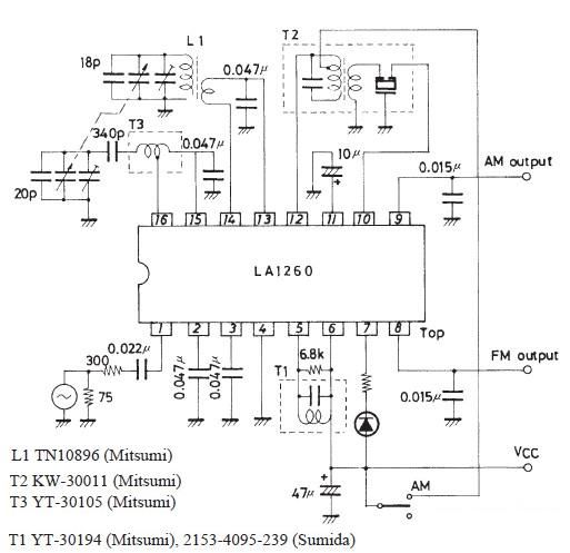
The FM IF MW radio receiver circuit schematic utilizes the LA1260 integrated circuit (IC) for AM and FM radio receiver electronic projects. The LA1260 incorporates numerous functions and features essential for radio receiver applications, including a high signal-to-noise ratio...