
HAM RADIO SW RECEIVER

The described radio receiver circuit operates as a direct-conversion receiver, allowing for efficient signal processing from amateur radio bands. The input bandpass filters are critical for isolating the desired frequency range, enhancing the receiver's ability to select specific amateur radio signals while rejecting out-of-band interference. The RF amplifier (VT1) boosts the incoming radio frequency signal, providing sufficient gain to ensure effective mixing in the diode mixer (VD1, VD2).
The mixer is pivotal in converting the RF signal to an intermediate frequency (IF), which is then processed by the audio frequency amplifier (VT3-VT5). This amplifier stage is designed for high gain to ensure that the audio signal is adequately amplified for headphone output (BF1), facilitating clear audio reception of the selected amateur radio transmissions.
The local oscillator (VT2) plays a crucial role in the frequency conversion process, generating a signal that is half the frequency of the incoming RF signal. This is achieved through the tuning capability provided by the variable capacitor (C27), allowing the user to adjust the local oscillator frequency to match the desired reception frequency.
The inclusion of the switch (SA1) for band selection simplifies the operation of the receiver, enabling users to easily switch between different amateur bands without complex adjustments.
The voltage regulator circuit, utilizing the Zener diode (VD3), ensures stable operation of the local oscillator by providing a consistent voltage supply, thereby reducing frequency drift that could occur due to variations in the supply voltage. This stability is essential for maintaining reliable reception across the various amateur bands.
Overall, the described circuit is a straightforward yet effective design for a radio receiver, making it suitable for amateur radio enthusiasts seeking to operate within the specified shortwave bands.A simple radio receiver circuit is shown in Fig. 1. This receiver is designed for reception of signals of amateur radio stations operating in the SW band of 10, 15, 20, 40 and 80 meters. This direct-conversion receiver consists of a set of an input bandpass filters tuned to the middle frequency of the amateur bands, a broadband RF amplifier based
on a transistor VT1, a diode mixer (VD1, VD2), a local oscillator (VT2) and a three-stage amplifier of audio frequency with high gain based on a transistors VT3-VT5. This amplifier is loaded with a headphones BF1. A switch SA1 is intended to switch between bands, it connects the filters to the input of the RF amplifier, and the mixer - to a corresponding resonant tank of the local oscillator.
The local oscillator is tunable by a variable capacitor C27 and it generates an oscillations with a frequency twice lower than the frequency of received signals. A simple voltage regulator is based on the Zener diode VD3 and it is used to reduce a dependence of the local oscillator frequency of a supply voltage variation.
🔗 External reference
Related Circuits
There are instances when a radio station can be found, and other times when no stations are detectable. The primary issue while tuning appears to be that any movement of the hands or body, such as releasing the tuning...
The second half controls the steering. The mechanical design is a 3 wheeled caddy with the single wheel actually a closely spaced pair of wheels which are driven by the main drive motor to provide motive power (this is...
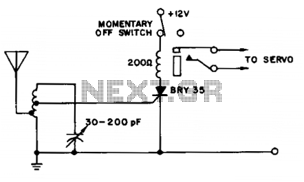
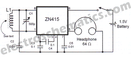
A simple and effective receiver for actuating garage doors, alarms, warning systems, etc. The SCR, which has a very low trigger current of 30 µA, requires an input power of only 30 µW to activate the relay. A high...
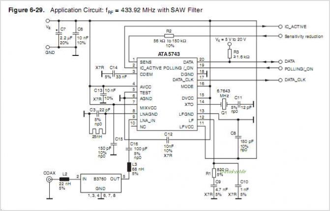
The ATA5760 and ATA5761 are multi-chip PLL receiver devices provided in an SO20 package. They have been specifically designed to meet the requirements of RF low-cost data transmission systems with data rates ranging from 1 kBaud to 10 kBaud,...
The FM radio receiver with PLL designed by A. Zaharov continues to attract the interest of radio amateurs. According to a publication in the magazine "Radio," one of the primary drawbacks of this type of detector is its low...
For this radio, which I repaired for someone, I made this DIY VL1. Later I found the real tube. The circuit described involves a DIY VL1 radio project, which suggests a focus on vacuum tube technology. The VL1 likely refers...