
CW Radio with Tubes

The circuit described involves a DIY VL1 radio project, which suggests a focus on vacuum tube technology. The VL1 likely refers to a specific type of vacuum tube or a particular circuit design intended for radio frequency applications. In constructing a DIY radio using vacuum tubes, several key components and design considerations are typically involved.
The primary components of a vacuum tube radio circuit include the vacuum tube itself, which functions as an amplifier or oscillator, and passive components such as resistors, capacitors, and inductors that help shape the signal. The power supply must be carefully designed to provide the necessary voltages for the tube operation, typically involving high voltage for the anode and lower voltages for the filament.
In the context of a radio receiver, the circuit may include an antenna input for capturing radio signals, a tuning circuit for selecting the desired frequency, and a detector stage for demodulating the audio signal from the RF carrier. Additionally, output stages may involve further amplification to drive a speaker or headphones.
When designing such a circuit, attention must be paid to component ratings, especially regarding high voltage and current levels associated with vacuum tubes. Proper layout and shielding are also critical to minimize interference and ensure stable operation.
In summary, the DIY VL1 radio project represents a classic approach to radio design, leveraging the unique characteristics of vacuum tubes to create a functional radio receiver. The eventual discovery of the original tube indicates a potential enhancement to the project, allowing for improved performance or authenticity in the radio's operation.For this radio, which I repaired for someone, I made this DIY VL1. Later I found the real tube. 🔗 External reference
Related Circuits
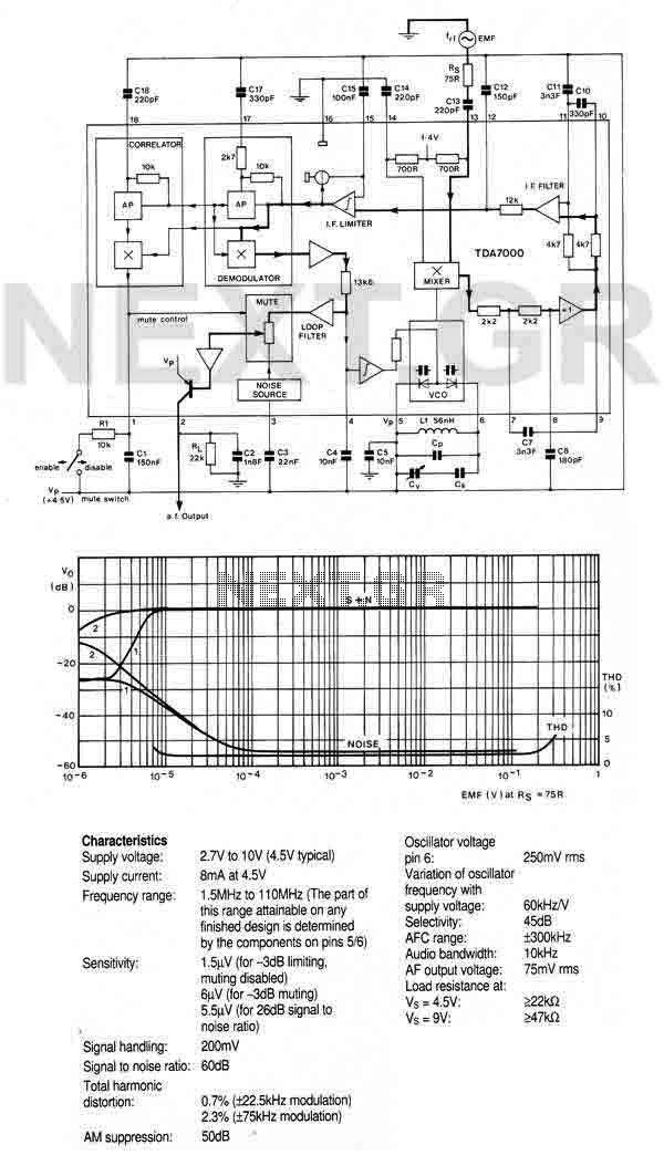
An FM radio integrated on a single chip that requires only a few basic peripheral components. Specifically, the chip needs only one simple coil, and its alignment is straightforward. The chip incorporates an RF input stage, mixer, local oscillator,...
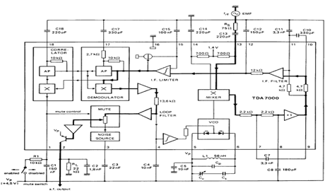
The TDA7000 is an integrated circuit (IC) designed for FM portable radios, featuring a Frequency-Locked Loop (FLL) system with an intermediate frequency of 70 kHz. It incorporates several functions, including an RF input stage, mixer, local oscillator, IF demodulator,...

This circuit is an FM radio receiver that is very small in size and operates effectively, although its sensitivity is limited. The principle of this circuit is based on the use of a generator. The FM radio receiver circuit typically consists...
This is a simple hardware computer interface and Linux program that can be used to control the most commonly used buttons on any consumer Family Radio Service (FRS) or General Mobile Radio Service (GMRS) radio. There are 22 available...
This project was inspired by a series of QST articles by Hayward, W1PH. The design is based on his April 1962 article, "Have You Tried 160 Lately." The rig features a simple, single-band configuration utilizing 6V6 tubes with regulated...
This circuit utilizes a ceramic tuning resonator with a frequency of 3.587 MHz, alongside resonator filters available at frequencies of 5.5 MHz, 7.7 MHz, and 10.7 MHz. The transmission range of the device is approximately 2-4 km. The circuit...