
How to improve the selectivity of the FM radio receiver

The FM radio receiver circuit designed by A. Zaharov embodies an innovative approach to enhancing selectivity and sensitivity in FM reception. The integration of a phase-locked loop (PLL) allows for precise tuning and stability. The use of an anti-parallel diode connection serves as a crucial modification to mitigate AM demodulation, thus improving the receiver's performance in environments with strong adjacent signals.
The construction of the coils L1 and L2 is critical; the choice of wire gauge impacts the inductance and resistance, which in turn affects the Q factor of the resonant tank circuit. The specified dimensions and winding techniques ensure optimal performance in the VHF band. The incorporation of an aluminum slug within coil L2 aids in tuning stability by providing a magnetic core that enhances inductance while minimizing unwanted oscillations.
The tuning capacitors and resistors are adjustable to cater to varying signal conditions and desired sensitivity levels. The selection of diodes with appropriate capacitance characteristics is essential for maintaining the integrity of the signal path and ensuring that the receiver operates efficiently without self-oscillation.
Testing in urban environments demonstrates the receiver's capability to function effectively in real-world scenarios, highlighting its robustness against interference. The option to implement an electronic tuning circuit broadens its usability, allowing for fine-tuning across the entire VHF FM spectrum, thus making it a versatile choice for radio enthusiasts and professionals alike.The FM radio receiver with PLL designed by A. Zaharov [1] still attracts the attention of radio amateurs. As noted in a publication of the magazine "Radio" [2, 3], one of the major drawbacks of this type of detectors is the low adjacent channel selectivity. The reason for this is the direct detection of strong signals by base-emitter junction of t ransistors connected across a source of AC signal voltage. To prevent direct AM demodulation of the signal it is recommended to use anti-parallel connection of diodes in the mixer circuit. The diode mixer can be connected in parallel to the signal source (Fig. 1) or in series with it (Fig. 2). To prevent direct demodulation of the signal with this method, in the circuit of A. Zaharov it takes to connect a diode in reverse direction across the base-emitter junction of the transistor VT1 (Fig.
3). But we can not do it, because in this case, the diode will be closed by the voltage of the base - emitter junction of the transistor. To overcome this difficulty it takes to connect the diode in series with the base - emitter junction to DC, and in anti-parallel to AC (Fig.
4). The locking range of this modified receiver is wider then the locking range of previously described receivers. It is useful to reduce the Q factor of the resonant tank circuit L2C7. To do this, wound the coil L2 with thinner wire (0. 2. 0. 3 mm in diameter (AWG 32. 29), or add into the tank circuit L2C7 an additional resistor R5 (0. 5. 2 ohms). In the modified receiver the coils are used similar to those used in circuit of the FM receivers with PLL.
The coil L1 is formerless with the diameter of 5 mm, the winding step is 1 mm and the number of turns is 6 of the wire 0. 5 mm (AWG 24). The coil L2 is wound on a frame with the diameter of 6. 5 mm, it has 9 turns of the wire with diameter of 0. 27 mm (AWG 30). The winding step is 1 mm. This coil L2 has a slug made of aluminium pipe with the length of 20 mm and diameter of 5 mm. Tweak the capacitors C2 and C7 to tune the receiver to the VHF band (65. 8. 73 MHz). Tweak the value of the resistor R1 to get maximum sensitivity of the receiver. To prevent self oscillation at audio frequency, the capacitance of the diode VD1 should be considerably smaller than the emitter junction capacitance of the transistor VT1.
This condition is fully satisfied by using diodes KD521 or KD522 (any of this series). The value of the capacitor C6 depends on the operating mode of the receiver (mono or stereo). In the schematic diagram shown in Fig. 4, the shown capacity is intended for a mono version. For the stereo version, it should be five times less. The FM receivers with PLL has been tested in city of Minsk, Belarus. The receiver was able to receive all four local FM radio stations with no interference between them, but in the pauses were heard interference of the television signal of the first and third TV channels. After modification the receiver the interference are gone. The anti-parallel connection of the diode VD1 and the base-emitter junction of the transistor VT1 work as signal limiter circuit for the signals of power radio stations.
In the modified receiver can be used an electronic tuning circuit (Fig. 5), in which a transistor KT315 (with any letter index) is used instead of the varicap. This tuning circuit powered by 3 volt can overlap whole the standard VHF FM band(65. 8. 73 MHz). 🔗 External reference
Related Circuits
This reflex radio project was inspired by Robert Bazian's design. His reflex radio is the "darndest" thing I have seen and his spectacular results inspired me to come up with my own version! These designs are similar to two-transistor...

This article discusses a simple 5-channel radio remote control circuit utilizing the TX-2B and RX-2B integrated circuits from Silan Semiconductors. The TX-2B/RX-2B is a remote encoder-decoder pair suitable for remote control applications. It features five channels, a wide operating...
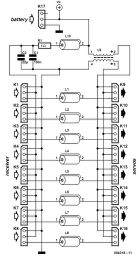
Receiver interference is a common issue among model builders. Preventive measures, such as ferrite beads fitted to servo cables, are frequently employed in larger models and electrically driven models to prevent the cables from acting as antennas and radiating...
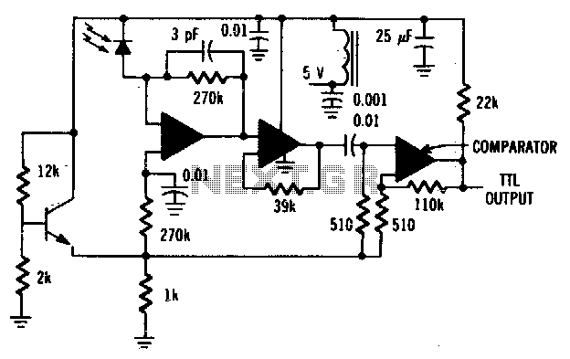
The MFODllOO PIN diode requires shielding from EMI. The MFODllOO PIN diode is a semiconductor device that operates as a switch or rectifier in various electronic circuits. To ensure optimal performance and reliability, it is essential to provide adequate shielding...
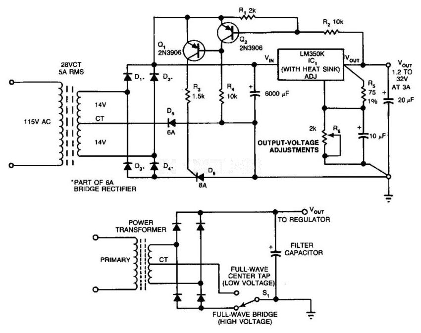
In this circuit, a full-wave bridge is switched to a full-wave center tap to reduce regulator dissipation. SCR D6 switches between configurations. When D6 is off, the circuit is an FWCT rectifier using D1, D2, and D5. It applies...
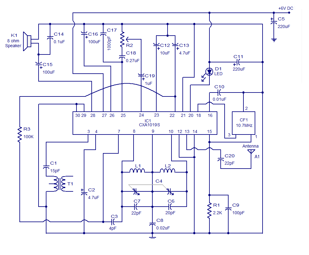
It is a high-quality FM receiver circuit based on the IC CXA1019. The CXA1019 is a monolithic silicon bipolar radio FM/AM receiver IC designed for Sony. The built-in circuitry within the CXA1019 includes an RF amplifier, mixer, oscillator, amplifier,...