
Hammond T-100/T-200/T-500 MIDIvice

Wiring is reduced to a minimum of 5 wires to each manual. You can choose one of 44 GM program setups by simply pressing a pushbutton and one of the manual keys. You may change the default MIDI program change sequences (256 Bytes per setup) stored in EPROM to your own needs.
Best of it: You will find schematics, printed circuit layout and EPROM HEX file here - it`s freeware! Interested First download the complete MIDIvice 1. 0 schematics. MIDIvice consist of three major parts: The MIDIvice Controller Board, the Keyscan Units (you need one PCB for each 8 keys, i.
e. 12 boards for a spinett organ) and a very simple "user interface" Panel. Wiring is extremely easy due to the serial 5-wire-interface to the keyscan units which fit snugly behind the key combs (see right picture above). Download the MIDIvice PCB layout PDF and etch boards as needed. Instructions how to etch a PCB from a printed layout can be found around the web, but I suppose you have already done this before.
I do NOT recommend this as a beginner`s PCB etching project! The transformer has to be replaced with a 117V type for those living in US. Warning: There are dangerous voltages present on the board when connected to mains power! For the freeware version 1. 01 of MIDIvice, omit IC6, IC7, IC8, MIDI in, lithium battery and extension connector (parts marked red) when furnishing the PCBs. The EPROM 27C256 IC5 has to be programmed with the MIDIvice spin44 firmware 1. 01 ; If you want the improved shareware version or need a programmed EPROM (10$ plus shipping), simply follow the "Buy Now" link below or drop me a line.
Percussion or brush contacts (first/upper row of contacts under the manual keys) may be connected directly to the Keyscan Units without removing the attached 220kOhm resistors. You may bring the lower manual in a working position by loosening it`s screws and tilting down so it is very easy to access.
I mounted the PCBs by simply glueing them to the sheet metal frame with hot glue, using a thin spacer strip to prevent short circuits. Don`t forget to connect the busbar wire to a ground pin of one of the Keyscan Units. 5 wires of the last lower Keyscan Unit lead to the MIDIvice Controller Board, separately for each manual.
MIDIvice provides an output for single-trigger percussion on T-Series organs, since the percussion contacts in the upper manual are used for MIDI scanning. Just reconnect the red/white percussion busbar cable from the Hammond percussion board to the /Persussion output of the MIDIvice Controller Board with a 47kOhms resistor in series.
So you don`t need my percussion modification circuit. MIDIvice transmits on two consecutive MIDI channels (jumper-defined Base Channel on upper manual, Base Channel +1 on lower manual). Future Versions will provide Base Channel +2 for bass pedals. Four jumpers on the MIDIvice controller board set the base octave and channel configuration - see schematics.
Default (=no jumper) MIDI upper manual channel is 1 (lower manual +1 = 2), default MIDI note on lower manual is 0x1D (F1), on upper manual 0x29 (F2). MIDIvice uses a simple two pushbutton "user interface". Pressing the "ProgChange" momentary switch blinks the adjacent LED and waits for a single key (lower manual) to be pressed.
Pressing the first F key on a spinett manual sends out MIDI Program Change to program 1. If you deci 🔗 External reference
Related Circuits
During a practice session on a Hammond C2 organ, the sound unexpectedly diminishes and becomes soft to the point of being inaudible. The Hammond C2 organ is an electromechanical instrument that utilizes a unique tonewheel generator system to produce sound....
Assistance is needed in analyzing a circuit, specifically regarding the frequency cut-off between the bass and treble channels. The potential cut-off frequencies under consideration are 500Hz, 1KHz, or 5KHz. In audio processing circuits, the frequency cut-off point between bass and...
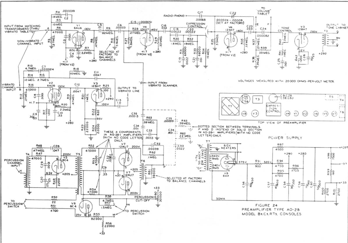
Construct a preamplifier intended to accept a 1/4" keyboard line-level signal and drive a Leslie 147 amplifier. The preamp will utilize a 12AX7 and 12BH7, following the design of a Hammond Organ preamp. The focus will be on the...
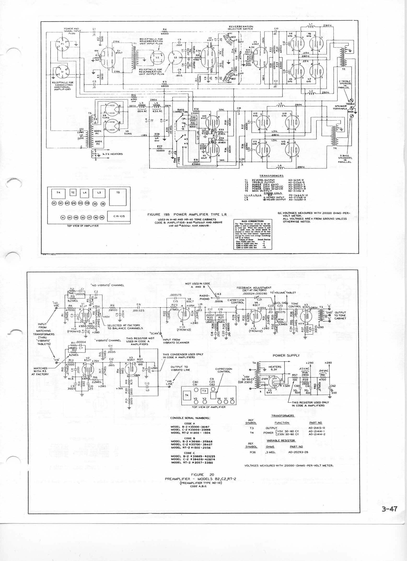
Designed in the 1950s, this preamplifier remained in production until 1975 and is still fully functional and serviceable today. This discussion aims to assist owners with basic troubleshooting and provides an in-depth look at circuit operation as well as...
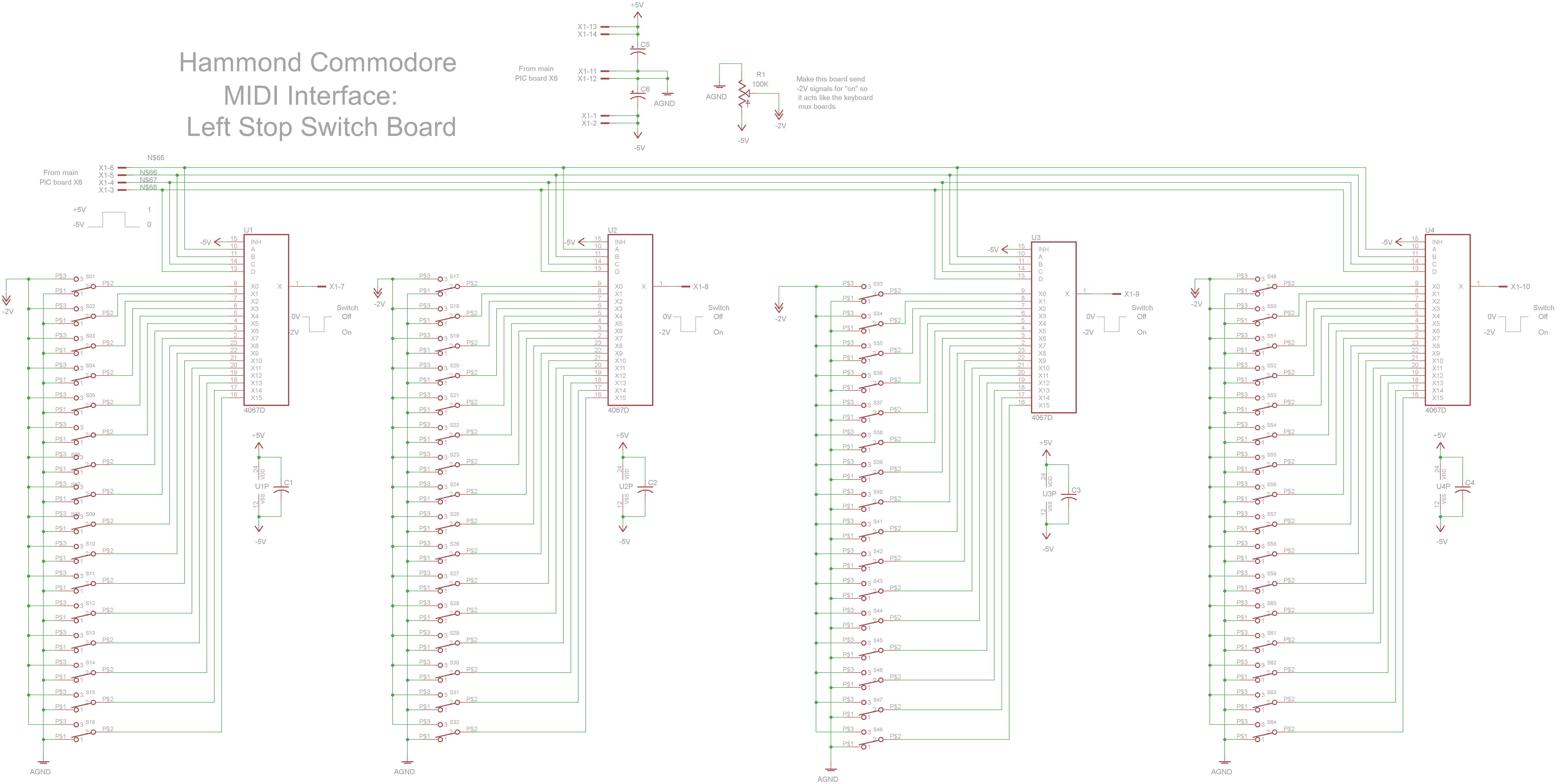
The schematic circuit board features switches that output -2V when activated and 0V when deactivated. Four 4067 multiplexers combine the 64 switch signals into 4 signals that return to the main PIC board. The circuit design incorporates a series of...