
Servicing the Hammond B-3 Type Pre-Amp

If you check the plate voltage for example and it reads low, then the plate load resistor R6 is probable going bad. (opening up) If however the voltage on the plate reads high, then the screen grid resistor R7 is going bad.
(opening up). The vibrato input is nearly the same as the above but for a few differences. First, the 1. 7Vdc is actually created here on V2 ²s pin 7. This reference voltage is used on several other tubes. Second, the output goes into the vibrato delay line driver tube. This is one-half of V3, the 12BH7A output tube. Again the plate and screen voltages should be checked on V2 like above. Additionally, the voltages on V3 should be checked. Any loss of amplification here will cause the vibrato to either be weak or not work. V4 is a dual triode tube. The first stage V4a accepts signals from the non-vibrato preamp, the vibrato scanner, and the percussion circuit. These signals are again amplified to a sufficient level to drive the expression control. The main service concern here would be the plate voltage. If the plate voltage is low, then the plate load resistor R29 is likely going bad (opening up). If it is high, and since there is no screen grid, the tube itself is likely going bad. In the expression control circuit, you will see there are two plates shown after V4(a), and a third movable plate shown going into the next stage of V4b.
The higher plate is connected directly to the output of V4a, while the lower plate has some RC (resistive/capacitive) circuits shown. If the movable plate is closer to the higher stationary plate, the volume is louder. As it moves to the lower stationary plate, it gets softer. Because of the RC network, the signal also gets a tone change. In other words, the high frequencies are attenuated faster than the lower frequencies. This means at lower volumes, the bass will actually remain more present than the highs. Since we hear different frequencies differently at different volumes, (see fletcher-munson curves ) this acts like a loudness curve in a home stereo.
The second stage of V4(b) picks up the signal from the expression control, amplifies it and sends it to the output stage through the tone control. Again the plate voltage is the primary check. Determine if the tube or plate load resistor is bad. A failure in either stage of V4 will usually kill all sound in the organ. The tone control is a passive circuit and in reality, it only attenuates the highs. It can be a source of problems if the potentiometer R40 is scratchy. If you have the preamp turned up to expose the underside, always clean this pot with some good quality cleaner such as De-oxit.
Notice C22 which is a feedback capacitor in the second stage of V4(b). This cap takes some of the output from V4(b) and sends it to its input. Since the output is 180 degrees out of phase with the input, it reduces the gain of that stage. It is set at the factory and in general, you set it by turning the screw located in the expression box clockwise all the way in. Then turn it counter clockwise 1 1/2 turns. This should not be played with as a volume control. Even though it does affect the volume, it also affects the frequency response and should be set close to the factory setting.
Also notice the reference to the volume tablet and the E and F terminals. This is where the volume soft/loud tab connects. By shorting out C24, the volume is raised. I mention this because there is a typical problem where when switching the soft/loud tab, you hear a thump or pop. This is due to C23 going bad. (leaking DC) V3 is the final amplifier of the preamp. This 12BH7A is a dual triode where one stage is for preamp output and the other is used after the V2 vibrato preamp to drive the vibrato delay line.
The signal is taken from the tone control, goes into pin 7 input grid, and outputs on the plate to drive the output transformer. Obvious check points are pin 6 plate and pin 8 cathode. A shorted C26 could cause the cathode voltage to be low. An open R42 could cause it to go way up and result in little or no amplification. Output transformers rarely fail so a loss of plate voltage is unlikely. The transformer converts the single ended signal into a balanced signal. It`s output is the famous GG terminals. A quick check of the overall gain of the preamp is to turn the expression pedal all the way up. Pull out the four lower drawbars on either manual. Play a C chord in the middle of the manual. You should read about 3 to 4 Vac across the GG terminals. The percussion channel input terminal H gets its signal from the percussion switches. Either the second or third harmonic. The signal enters T4 transformer and V5 (6C4), the first stage of amplification. Not many problems in this circuit other than the occasional tube failure. T5 takes the single ended signal and changes it to a balanced signal. It drives the balanced amplifier V7 (12AU7A). Notice the third winding on T5. This carries the selected percussion harmonic that was borrowed from its drawbar back and replaces the borrowed harmonic through R50 and terminal J.
By changing the voltage on the input grids, the gain of V7 can be varied. This is done through the center tap of T5 ²s secondary winding controlled by V6 (6C4). The percussion cutoff control sets the bias of V7 which adjusts the decay speed of the percussion. When a key is depressed the signal first plays loudly through the control tube, transformer T6, a high pass filter, and terminal D to the grid of V4. Immediately condenser C31 in the control tube grid circuit begins to discharge, causing the signal to fade away.
Terminal K (Approx 25Vdc) is connected to the 1 ² drawbar wire which is connected to the manual busbar. When an upper manual key is pressed, terminal K is grounded through the tone generator filters. This virtually grounds the plate of V6 (connected as a diode), stops conduction, and isolates cathode and control tube grid circuit.
The grid then drifts from approx +25Vdc to about +15Vdc, at a rate determined by the time required for C31 to discharge through R57 and R58. At the completion of this sequence the percussion signal is blocked. No further percussion effects occur until all keys of the upper manual are released and the control grids can again rise to +25Vdc.
The rate of this rise is fixed by the time required to charge C31 to +25Vdc through R55 and R56. With all three percussion tubes removed, the organ will play normally, just no percussion. The transformers give little to no trouble but can fail. In some cases, cause static that can only be removed by replacing the offending transformer. In an emergency, you can pull the percussion tubes to get rid of the static and operate the organ with no percussion. These transformers are NLA but can be acquired from used instruments including the smaller and much cheaper M-3 series organs.
To set the percussion cutoff control, depress a key with no drawbars out and the percussion on. The sound should fade out completely. Adjust the control until the sound can be heard. Then turn it the other way until if fades out completely. You can further adjust it for the amount of decay you prefer. 🔗 External reference
Related Circuits
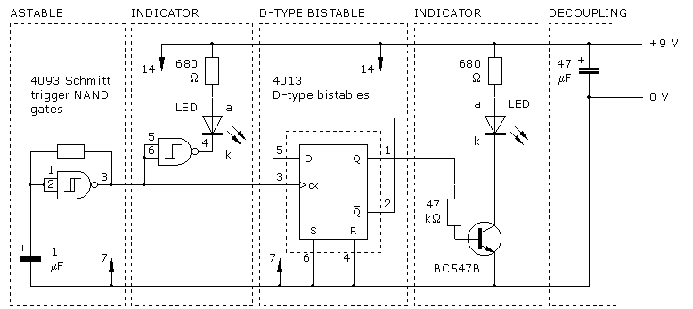
The CLOCK input indicates that it is edge-triggered, responding to abrupt changes in voltage rather than gradual changes or steady logic levels. The CLOCK input of the 4013 D-type bistable is specifically rising-edge triggered, meaning it only reacts to...
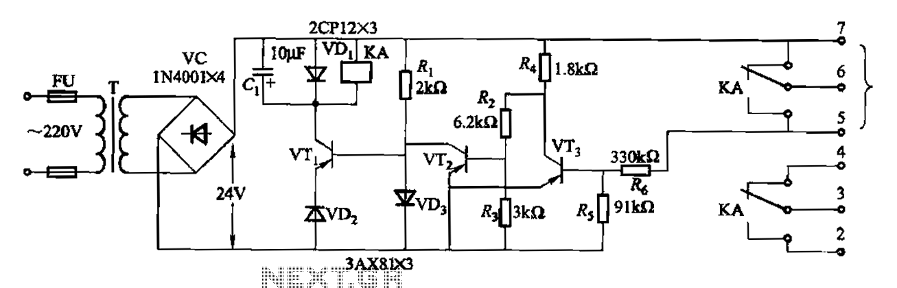
Another JYB type liquid level controller internal circuit is shown. This circuit employs a Schmitt trigger configuration, enhancing the reliability of the action level controller. The JYB type liquid level controller utilizes a Schmitt trigger circuit composed of transistors VT2...
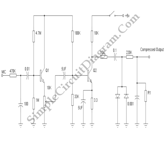
Signal clipping is typically avoided in most applications; however, there are specific instances in audio processing where clipping is intentionally utilized for beneficial effects. Signal clipping is a phenomenon that occurs when an audio signal exceeds the maximum amplitude that...
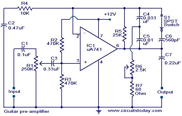
A preamplifier circuit designed for high-impedance electric guitar pickups is presented. This circuit utilizes a uA 741 operational amplifier (IC1) configured as a non-inverting amplifier. The potentiometer R1 functions as a volume control, while potentiometer R6 serves as a...
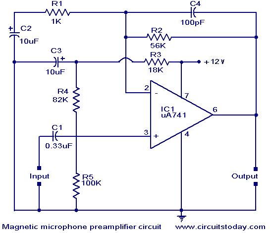
A preamplifier for magnetic pickups of record players is presented. The uA 741 is utilized as an AC-coupled non-inverting amplifier operating on a single supply. The amplifier gain is determined by the feedback components, where C2 manages the low-frequency...
The tuned circuits of capacitance and inductance used in vacuum tube transmitter circuits are often referred to as "tank" circuits, as they serve as reservoirs of RF energy. Blocking capacitors are employed to create a high impedance path for...