
Hammond Commodore MIDI Interface

The circuit design incorporates a series of switches, each functioning as a binary input that determines the output voltage level. When a switch is in the "on" position, it generates a consistent output of -2V, while in the "off" position, the output is 0V. This voltage differentiation is crucial for the subsequent processing stages.
The four CD4067 analog multiplexers serve a vital role in managing the numerous switch outputs. Each multiplexer is capable of handling 16 input signals, allowing for the effective consolidation of the 64 switch outputs into 4 distinct signals. This is accomplished through the selection lines of the multiplexers, which are controlled by the main PIC microcontroller. The microcontroller can select which of the 64 switch signals to route through the multiplexers, thus significantly reducing the number of lines required to communicate with the PIC board.
The integration of these components ensures efficient signal management and processing, allowing for a streamlined approach to handling multiple inputs from the switches. The design is particularly useful in applications where space and efficiency are paramount, enabling complex control systems to be implemented with minimal hardware. Proper attention to the power supply and grounding is essential in this circuit to prevent noise and ensure reliable operation of the multiplexers and the PIC microcontroller.Here is the schematic circuit board. Each switch puts out -2V when it`s on and 0V when it`s off. The four 4067 chips multiples the 64 switch signals into 4 signals that go back to the main PIC board. 🔗 External reference
Related Circuits
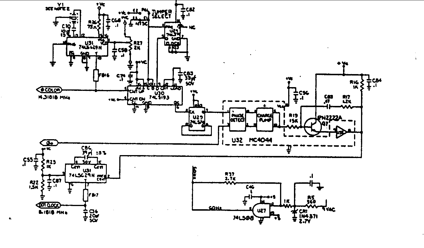
Crystal Y1 generates a fundamental frequency clock signal of 14.31818 MHz. U31 is a Dual Voltage Controlled Oscillator (VCO) that produces a 14.31818 MHz clock signal, referred to as the color clock, at pin 10. The output frequency can...
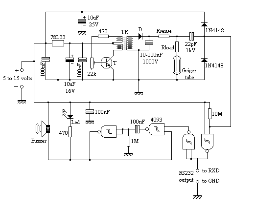
The circuit employs common building blocks. The high-voltage power supply is a classical oscillator circuit utilized in various applications where low current and high voltage are required. The transformer (TR) is a step-up transformer salvaged from a xenon light...
The circuit features a serial coded modulated control signal that amplifies and transmits high-voltage isolation. It utilizes a 556 timer-based circuit along with resistors R1, R2, capacitors C1, and R3, R4, C2 to form two astable multivibrators. The circuit...
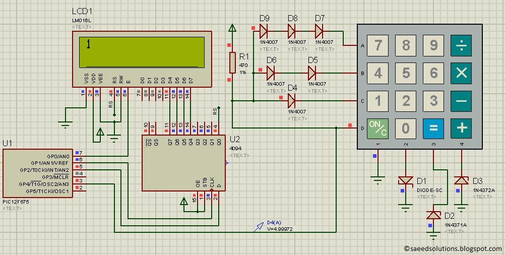
This post provides a simple method to interface any keypad (e.g., 4x4 or 4x3) with the PIC12F675 microcontroller. The code for the PIC12F675 is written in C language. The interfacing of a keypad with the PIC12F675 microcontroller involves several key...
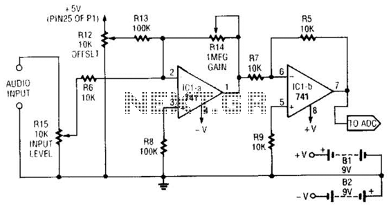
This simple general-purpose driver for an analog/digital converter uses two 741 IC devices with adjustable gain and offset. Other op-amps might be substituted, but some circuit adjustments might be needed. The circuit consists of two operational amplifiers (op-amps) from the...
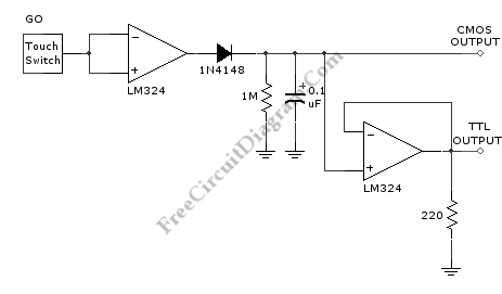
This is an interface circuit for digital data input. The circuit consists of a touch button, an operational amplifier (op-amp), a diode, a capacitor, and resistors. Any conductive surface can be used. The interface circuit designed for digital data input...