
Hardware circuit C51 microcontroller serial communication

The schematic for the serial communication circuit incorporates the MAX232 level shifter, which facilitates the conversion of TTL signals from the microcontroller to RS232 levels, making it compatible with standard serial communication interfaces found on computers. The MAX232 typically has a set of capacitors connected to its pins that are crucial for its operation, providing the necessary charge pumps for the level shifting process.
In this configuration, the RXD line from the computer connects to the TXD line of the microcontroller, allowing data to be received by the microcontroller. Conversely, the TXD line from the microcontroller is connected to the RXD line of the computer, enabling data transmission from the microcontroller to the computer. The ground (GND) connection is essential to maintain a common reference point for both devices, ensuring stable communication.
The use of a three-wire connection simplifies the design, reducing the number of connections required while maintaining the functionality needed for effective serial communication. The circuit's robustness can be enhanced by including bypass capacitors close to the power pins of the MAX232 to filter out noise, which could potentially disrupt the communication process.
Overall, this setup provides a reliable means of establishing serial communication between a 51 microcontroller and a computer, leveraging the capabilities of the MAX232 for level shifting and ensuring compatibility between different voltage levels used by the devices.51 microcontroller has a full-duplex serial communication port, so you can easily serial communication between the microcontroller and the computer. When the serial communicati on to meet certain conditions, such as PCs serial port is RS232 level, while the microcontroller is TTL level serial port, there must be a level conversion circuit between the two, we were using a dedicated chip MAX232 conversion, although you can also simulate the conversion with a few transistors, but still with a special chip easier and more reliable. We use a three-wire serial connection, which means that the computer and the 9-pin serial connector which is only three lines: 5 feet GND, RXD 2 feet, 3 feet of TXD.
This is the easiest connection method, but enough for us to use the circuit as shown below, 11-pin connector MAX232 pin 10 and the microcontroller, 9 feet and the microcontroller 10-pin connector, and the first 15 feet MCU 20-pin connector. Serial communication hardware circuit as shown below.
Related Circuits
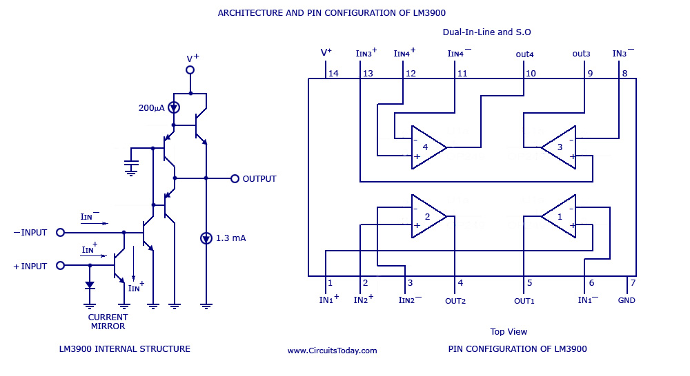
A simple multi-channel audio mixer circuit utilizing the LM3900 quad amplifier is presented below. The circuit features a four-channel quad amplifier (LM3900) with two microphone audio inputs and two direct line inputs. By paralleling additional circuits, the number of...
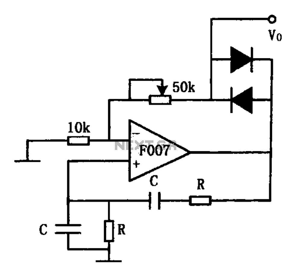
The stable sine wave oscillator circuit is designed to maintain consistent oscillation. The loop gain must be carefully managed; if the gain is excessive, waveform distortion occurs, while insufficient gain can lead to cessation of oscillation. This circuit employs...
In all the houses exist the bells in the door. All want, they have the possibility of being possible to change the intensity, the tone of sound. With this circuit we have this possibility. With the materials round the...

A Countdown Timer Circuit is a project submitted by a group of students for their ECE 130 - Computer Application class on August 31, 2006, at the University of St. La Salle, Philippines. The seven-segment decoder is utilized in...

The relay power in the linear circuit is derived from a -120 V bias supply, while the transmit keying output from the Kenwood device is +12 V with a maximum current of 10 mA. A critical component of this...
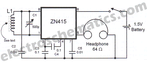
There are instances when a radio station can be found, and other times when no stations are detectable. The primary issue while tuning appears to be that any movement of the hands or body, such as releasing the tuning...