
Relay Interface For Amateur Radio Transceivers Circuit

The described circuit features a relay that operates from a negative bias voltage of -120 V, which is essential for the linear amplifier's functionality. The relay is activated by a transmit keying signal sourced from a Kenwood device, delivering a +12 V signal with a maximum current capability of 10 mA. This configuration allows for efficient control of the relay, enabling it to switch the high-voltage line as required for transmission.
The PNP driver transistor plays a pivotal role in this setup. It is selected for its ability to manage high voltage levels, specifically rated for a minimum of 150 V, which ensures it can safely switch the relay without risk of breakdown. Additionally, the transistor is designed to handle a current of around 250 mA, providing sufficient drive capability to energize the relay coil effectively.
In practical applications, the circuit would typically include biasing resistors to set the operating point of the PNP transistor, ensuring it remains in the active region during operation. Protection components, such as diodes, may also be included to prevent back EMF generated by the relay coil from damaging the transistor when the relay is de-energized.
Overall, this circuit exemplifies a robust design for controlling high-voltage relay operations using a low-voltage control signal, ensuring reliable performance in linear amplifier applications. The relay power in the linear is obtained from the -120-V bias supply, and the transmit keying output from the Kenwood is +12 V at 10 mA maximum. The key ingredient in the circuit is the pnp driver transistor, which must be capable of handling at least 150 V at about 250 mA.
Related Circuits
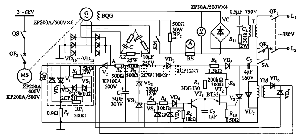
The circuit depicted in Figure 16-105 illustrates a synchronous motor. The components include BQ, which represents its field winding, and G, which denotes the AC excitation for the motor. The notation BQG indicates the field winding, with an empty...

This is a simple design of an audio level meter. The circuit utilizes a single integrated circuit (IC) and a minimal number of external components. It is based on the LM3915, which functions as the controller for the audio...
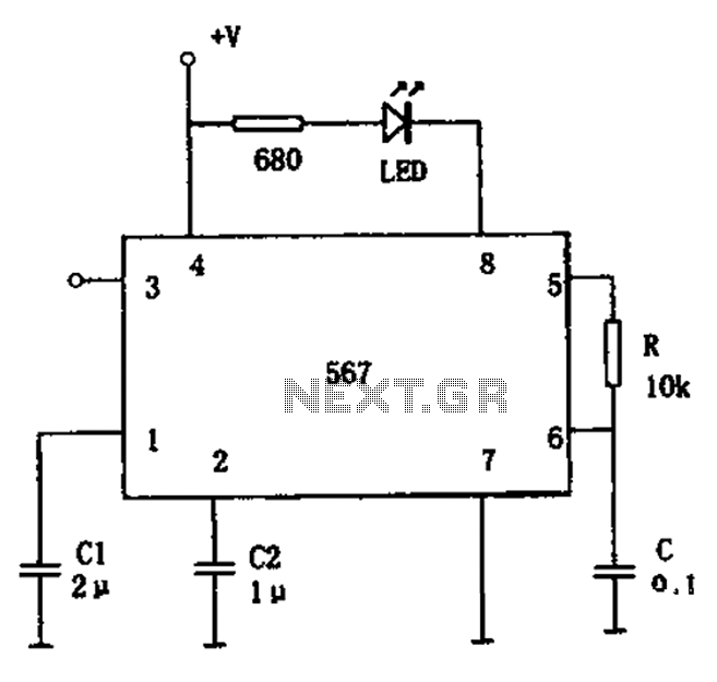
The FM demodulation circuit is illustrated in Figure 567. The FM signal is input at pin 3, and the demodulated signal is output from pin 5. The center frequency of the FM demodulation circuit is determined by the formula...
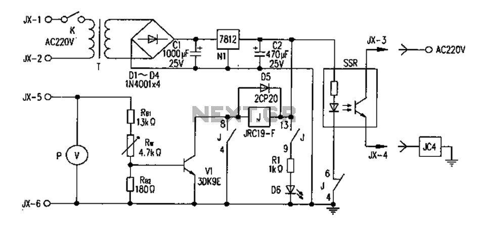
A telephone line-based audio muting and light activation circuit. Frequently, when listening to music or watching television at elevated volume levels, it becomes difficult to hear a telephone ring, resulting in missed important calls. This circuit is designed to address...
The FM302E-I-type FM transmitter exciter is utilized in Japan's NEC HPB a 1210 motherboard. It features direct carrier frequency modulation, phase-locked frequency stabilization, and frequency synthesis. The preamplifier (BLF-177 FET) is directly driven by an actuator, achieving a maximum...
The text of the Arduino reference is licensed under a Creative Commons Attribution-ShareAlike 3.0 License. Code samples in the reference are released into the public domain. The Arduino platform is an open-source electronics prototyping environment that enables users to create...