
HARTLEY OSCILLATOR

The Hartley oscillator operates on the principles of resonance and feedback, utilizing an inductor-capacitor (LC) tank circuit to generate oscillations. In this configuration, the two inductors (L1 and L2) are connected in series, with a capacitor (C) connected in parallel to the tapped coil. The feedback mechanism is crucial for sustaining oscillations, as it allows a portion of the output voltage to be fed back into the circuit to maintain the oscillation process.
The tank circuit's resonant frequency is calculated using the formula:
\[ f = \frac{1}{2\pi\sqrt{L_{\text{total}}C}} \]
where \( L_{\text{total}} \) is the equivalent inductance of the series-connected coils. For a Hartley oscillator, this can be expressed as:
\[ L_{\text{total}} = L1 + L2 \]
This equation showcases how the inductance values directly influence the oscillation frequency. The feedback fraction is critical, as it determines whether the circuit will sustain oscillations. The condition for oscillation is that the loop gain must be equal to or greater than one, which is achieved when the feedback voltage is appropriately scaled.
In practical applications, the Hartley oscillator is favored for its simplicity and effectiveness in generating sine wave signals. It is commonly used in RF applications, signal generators, and other electronic devices requiring stable oscillation frequencies. The design can be adjusted by varying the values of L1, L2, and C to achieve the desired frequency response, making it a versatile choice in electronic circuit design.The Hartley oscillator is an LC electronic oscillator that derives its feedback from a tapped coil in parallel with a capacitor (the tank circuit). Although there is no requirement for there to be mutual coupling between the two coil segments, the circuit is usually implemented as such.
A Hartley oscillator is essentially any configuration that us es a pair of series-connected coils and a single capacitor. In the oscillator, the feedback voltage is developed by the inductive voltage divider, L1 & L2. Since the output voltage appears across L1 and the feedback voltage across L2, the feedback fraction is As usual, the loading effect of the base is ignored. For oscillations to start, the voltage gain must be greater than 1/ ². The frequency of oscillation is given by 🔗 External reference
Related Circuits
The circuit was designed to create an electronic oscillator known as the Wien Bridge Oscillator, which can be used for the generation of low-frequency sine waves. The Wien Bridge Oscillator is a type of electronic oscillator that generates sine waves....
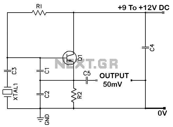
Colpitts 1 MHz to 20 MHz Crystal Oscillator Circuit. This is a simple Colpitts crystal oscillator for frequencies ranging from 1 to 20 MHz. The parts list includes: R1 - 220 kΩ, R2 - 1 kΩ, C1 - 82...

This oscillator may contain several switched crystals to provide channelized operation. A buffer amplifier may be added if desired. The oscillator described is designed to utilize multiple switched crystals, enabling it to operate across various frequency channels. This feature is...
One of the significant challenges in designing vacuum-tube oscillators is maintaining a constant frequency despite mechanical vibrations, temperature fluctuations, voltage variations in the supply lines, and changes in the load power drawn from the circuit. The effects of variable...
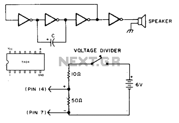
This simple circuit utilizes the 7404 low-power Schottky hex inverter. Capacitor C is a 5 to 30 µF electrolytic capacitor selected for the desired pitch. The speaker is a 2-inch, 8-ohm unit. The circuit employs a 7404 low-power Schottky hex...
The FV-1 features internal circuitry that supports an external crystal, ideally a 32.768 kHz watch crystal. These crystals are very affordable and readily available. While other frequencies are available, they are not as cost-effective or common. If the system...