
The FV-1 Crystal Oscillator

The FV-1 integrated circuit (IC) is designed for audio applications, particularly in effects processing, and requires careful consideration regarding its clocking mechanism. The choice of a 32.768 kHz watch crystal is optimal due to its cost-effectiveness and availability, allowing for the efficient functioning of the device. When integrating the FV-1 into a system, it is essential to consider the characteristics of the chosen crystal oscillator. The high internal resistance of the watch crystal necessitates careful handling to prevent loading effects that may disrupt the oscillator's operation.
The suggested addition of a 15 pF capacitor from the X2 pin to ground is a critical design consideration. This capacitor helps stabilize the oscillator circuit and ensures that various crystal types can operate effectively, mitigating potential startup issues. The limitation of the FV-1's response to 15 kHz should be acknowledged, particularly in the context of audio effects where higher frequencies may not significantly contribute to perceived sound quality.
For applications targeting audiophiles, the use of a watch crystal is sufficient; however, for those who prioritize specifications, a higher frequency clock, such as 48 kHz, may be advantageous. The ability to use a 6 MHz resonator that can be divided down to 46.875 kHz illustrates the flexibility of the FV-1 in accommodating different operational requirements.
Furthermore, the integration of an adjustable oscillator allows for creative control over reverb size and other effects, enhancing the versatility of the FV-1 in audio design. This feature enables users to explore unique sound textures by manipulating the clock frequency, thus leveraging the distinct filtering characteristics of the ADC and DAC components. The design of such an oscillator circuit should consider smoothing techniques to prevent abrupt changes in frequency, ensuring a seamless user experience.
Overall, the FV-1 provides a robust platform for audio effects processing, with various considerations for crystal selection, circuit design, and user interaction that can significantly impact the final audio output.The Fv-1 has internal circuitry to support an external crystal, preferably a 32768Hz watch crystal. These crystals are extremely inexpensive and widely available. Frequencies other than 32768Hz are available, but not as cheap and not as plentiful. If the system the FV-1 is integrated into has local clocks available, a logic level clock signal can be directed to pin X1 of the FV-1 through a small resistor, on the order of 10K ohms. Crystal oscillators for these low cost crystals are very different from oscillators designed for megahertz range crystals and resonators. The watch crystal oscillator has very high internal resistances, on the order of 10M ohms. When attempting to observe the crystal signals, the loading of a 10X scope probe can load the crystal terminals to the extent that the oscillator may stop working altogether.
Further, leakage across the PCB could cause problems, so be sure to have the product board well cleaned after assembly, if this is not a normal part of your PCB processing. Leakage should only become a problem in the case of very poorly assembled product. NOTE: Some small 32KHz crystals have been found to operate in 3rd overtone mode during startup. It is suggested that the EC-38 style crystal should work well with the FV-1, but smaller crystals have shown problems.
In any case, the addition of a 15pF capacitor from the X2 pin to ground will allow all crystal types to function properly. The 32768 clock frequency causes the overall response of the FV-1 to be limited to 15KHz. This may seem insufficient for a quality audio product, but in the case of reverb and most effects, response beyond this range is unnecessary.
My own hearing is limited to about 13KHz, and has been since I was in my 20s; neither of my children have been able to hear beyond 16KHz since I began testing them at an early age. Most adolescents and adults can only hear signals above 15KHz as faint `impressions` as opposed to actual sounds.
Our idea of the human hearing response being 20Hz to 20KHz is out of convenience. That `20 to 20` range is easy to remember and speak, but is not true. There really is no lower limit of hearing if one considers earthquakes within our `hearing` range, as they are most obviously sensed; perhaps the lower limit of our actual hearing is perhaps 50Hz, where most of us are actually hearing the gross distortion products of headphones and low end drivers at these frequencies. If you listen to a really clean subwoofer, you`re only feeling the result, and probably will miss the bass harmonics, as we are used to bass having fairly severe distortion!
Perhaps we should say our hearing range is 50 to 15K, but then that would be heretical in the Church of Modern Audio, no So, if your product is targeted toward those that are interested in excellent sound, a watch crystal should suffice. If your product is targeted toward customers that look at specs and only then decide how they like the sound, chose a 48KHz clock frequency.
This circuit can run an inexpensive 6MHz resonator and divide it to 46. 875KHz, which will easily allow 20KHz FV-1 signal path operation. Be advised: Precision may be important to you, but when it comes to effect design, there is nothing precise about it. SOUND is more important than any objective measurement you can make! As an added dimension to effects creation, the FV-1 can be clocked by a simple oscillator, made available as a variable to the user.
When allowing an adjustable clock, reverb size can be adjusted continuously, and the unique sound of the sharp filters within the ADC and DAC portions of the FV-1 can be exploited. Here`s an example of a simple oscillator for this purpose: You may wish to have the oscillator frequency `smoothed` so that slight discontinuities in the potentiometer element do not lead to abrupt changes in clock frequency.
This circuit may be useful: The output goes directly to the X1 pin, and should allow 🔗 External reference
Related Circuits
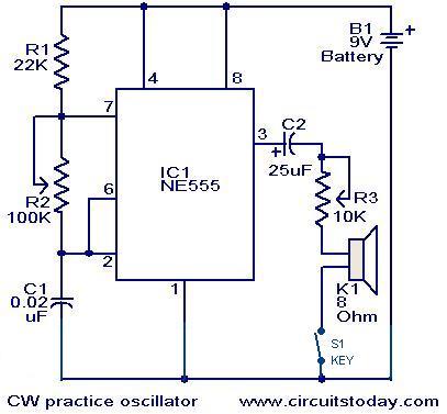
A circuit diagram for generating continuous wave (CW) Morse code is presented here. This circuit is particularly beneficial for individuals interested in practicing Ham Radio. It consists of an astable multivibrator utilizing the NE555 timer. The oscillation frequency of...
Millimeter-wave frequency bands are appealing due to their wide available bandwidths. Signals can be generated in various ways; however, for each type of oscillator, electronic tuning of the source in a defined and controlled manner is desirable. Employing a...
A quadrature oscillator generates two sine-wave signals, with one signal shifted 90 degrees from the other. The output that leads the other is referred to as cosine. A quadrature oscillator is an essential electronic circuit used to produce two sinusoidal...
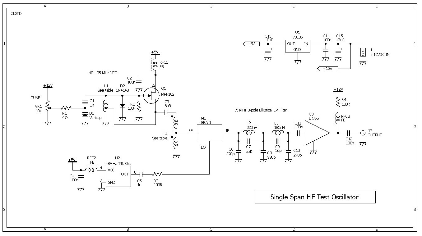
This compact RF oscillator operates across the entire frequency range of 0.4 to 30 MHz in a single sweep of the dial, featuring a terminated 50-ohm output of more than 300 mV throughout the HF band. Unlike most signal...
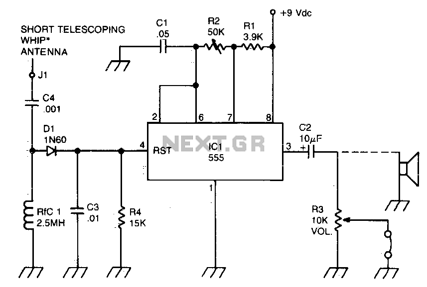
A sidetone oscillator is a specific type of audio astable multivibrator. Keying is achieved by turning the oscillator on and off through the application of a positive DC potential, which is generated from the RF signal to the reset...
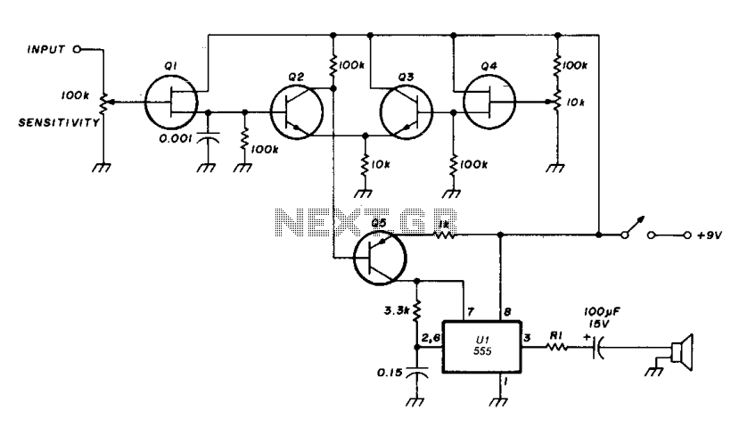
The transistor Q5 and the 1000-ohm resistor form the variable element necessary for controlling the frequency of the voltage-controlled oscillator (VCO) by limiting the charging current flowing into the 0.15 microfarad timing capacitor based on the forward bias applied...