
Electron-Coupled Oscillators

In the context of vacuum-tube oscillator design, the implementation of electron coupling provides a robust solution to frequency stability challenges. The Hartley circuit's adaptation, featuring a grid of wires instead of a solid plate, allows for the effective modulation of the electron flow, which is critical for achieving consistent oscillation frequencies. This innovative approach not only enhances the circuit's resilience to external perturbations but also facilitates the use of standard tetrodes and pentodes, which are integral to modern oscillator designs.
The tuning of the LC circuit plays a pivotal role in determining the overall performance of the oscillator. The Q factor, which is a measure of the circuit's selectivity and efficiency, must be optimized to ensure minimal energy loss and maximal stability. Engineers may achieve this by carefully selecting components with low equivalent series resistance (ESR) and high-quality capacitors, thereby reducing dielectric losses. Additionally, the design should incorporate a high grid-leak resistance to enhance the effective Q while ensuring that feedback mechanisms are kept to a minimum, thus promoting stable oscillations.
Moreover, the grounding of the suppressor grid in pentode configurations is a critical design consideration. This practice not only improves internal shielding but also contributes to the overall frequency stability of the oscillator. The careful management of the plate and screen voltage ratios further aids in maintaining consistent oscillation frequencies, reinforcing the importance of meticulous voltage regulation in oscillator circuits.
In summary, the integration of electron coupling and the optimization of circuit parameters are fundamental to the successful design of vacuum-tube oscillators. By addressing the various factors influencing frequency stability, including load variations, circuit Q, and component selection, engineers can create oscillators that meet the demanding requirements of modern electronic applications.One of the outstanding problems in the design of vacuum-tube oscillators is that of keeping the frequency constant despite mechanical vibrations, temperature changes, voltage variations in the supply lines, and changes in the amount of power taken out of the circuit by the load. The effects of variable loading are greatly reduced by the use of electron coupling. Let us imagine that in the Hartley circuit of Fig. 14 B the actual metal plate is replaced by a grid of wires. The stream of electrons reaching this electrode increases and decreases in number at the frequency of the oscillating circuit in the usual manner. But, with a grid of wires rather than a solid metal plate, a part of this stream of fluctuating electrons passes through the " plate " and can be used in a later portion of the tube.
It is as though we had a " virtual" cathode, emitting electrons, whose number varied from maximum to minimum periodically at a high rate. Of course it is impossible to heat and cool an actual cathode at high frequencies. Yet the combination of the Hartley circuit with a grid which acts as the " plate " serves the same purpose.
In the circuit on the left of Fig. 29 A, the fluctuating electron current, which has passed through the grids, reaches the solid plate and passes on to the tuned circuit LC. When the periodic fluctuations of the electron stream correspond to the natural frequency of the tuned circuit, they serve to supplant the losses in this resonant or tank circuit and keep it in oscillation.
An important feature of this arrangement is that the upper grid is operated at ground r. f. potential, and hence acts as a shield between the output or load circuit coupled to LC and the oscillating circuit itself. In this way, variations in the load current are prevented from reacting upon the oscillator circuit and changing its frequency.
We see in this circuit that the oscillator operates very much in the usual manner, but that the load circuit is " electron coupled " rather than direct, capacity, or magnetically coupled to it. At the right of Fig. 29 A, an untuned output circuit is shown. In this case, the output voltage and power are lower, lacking the " build up " which a tuned circuit gives, but the plate circuit has better isolation from the oscillator, and hence the frequency stability is greater.
Ordinary tetrodes and pentodes can be used in these oscillators. With a pentode, the suppressor grid should be grounded and not connected to the cathode, in order to give additional internal shielding of the load circuit from the oscillator circuit. Granting that the electron-coupled feature just described largely solves the problem of stabilizing frequency against load variations, we still have left the other possible influencing factors for consideration.
First in importance among these is the Q of the tank circuit of the oscillator. This must be as high as possible. It can best be obtained by making the L/C ratio of the circuit as low as possible. The resistance of the circuit is to be made low by winding the coil with large wire and by using condensers in which the dielectric losses in the insulation are low. The effective Q of the circuit is increased by using a high value of grid-leak resistance and by using the least possible feedback which will maintain stable oscillations.
Frequency stability will be greatest when the ratio of the plate to the screen voltage is about three to one. The plate supply should be free from ripple and may well be voltage-stabilized. In order to maintain frequency stability, constant strength, and freedom from harmonics, oscillators of the type just described should not be built to deliver large amounts of power.
They should be followed by power-amplifying equipment. Mechanical vibration, which causes frequency instability, can be avoided by care in the constructional details as, for example, the use of short leads, heavy chassis and panel m 🔗 External reference
Related Circuits
Unlike conventional small-signal methods, employing large-signal, time-domain design techniques facilitates the creation of low-noise grounded-base oscillators suitable for VHF/UHF applications. The development of low-noise grounded-base oscillators for VHF/UHF applications presents unique challenges and opportunities. By utilizing large-signal, time-domain design techniques,...
RC oscillators utilize resistors and capacitors to produce low or audio-frequency signals. Therefore, they are often referred to as audio-frequency (A.F) oscillators. RC oscillators are fundamental circuit designs utilized in various applications for generating periodic waveforms, particularly in the audio...
Hartley oscillators are inductively coupled, variable frequency oscillators that can be series or shunt fed. They feature a center-tapped inductor and a tuning capacitor, which simplifies the circuit construction. The schematic includes a buffer stage and an amplifier stage...
This article explains the construction and working of feedback oscillators, with a detailed description of the Wien bridge oscillator and phase shift oscillator, along with their circuit diagrams, basic components, and practical applications. Oscillators are electronic devices that produce...
The schematic illustrates the division of a crystal oscillator signal by the crystal frequency to achieve a precise 1-second time base with an accuracy of 0.01%. Two cascaded 12-stage counters (CD4040) create a 24-stage binary counter, with specific bits...
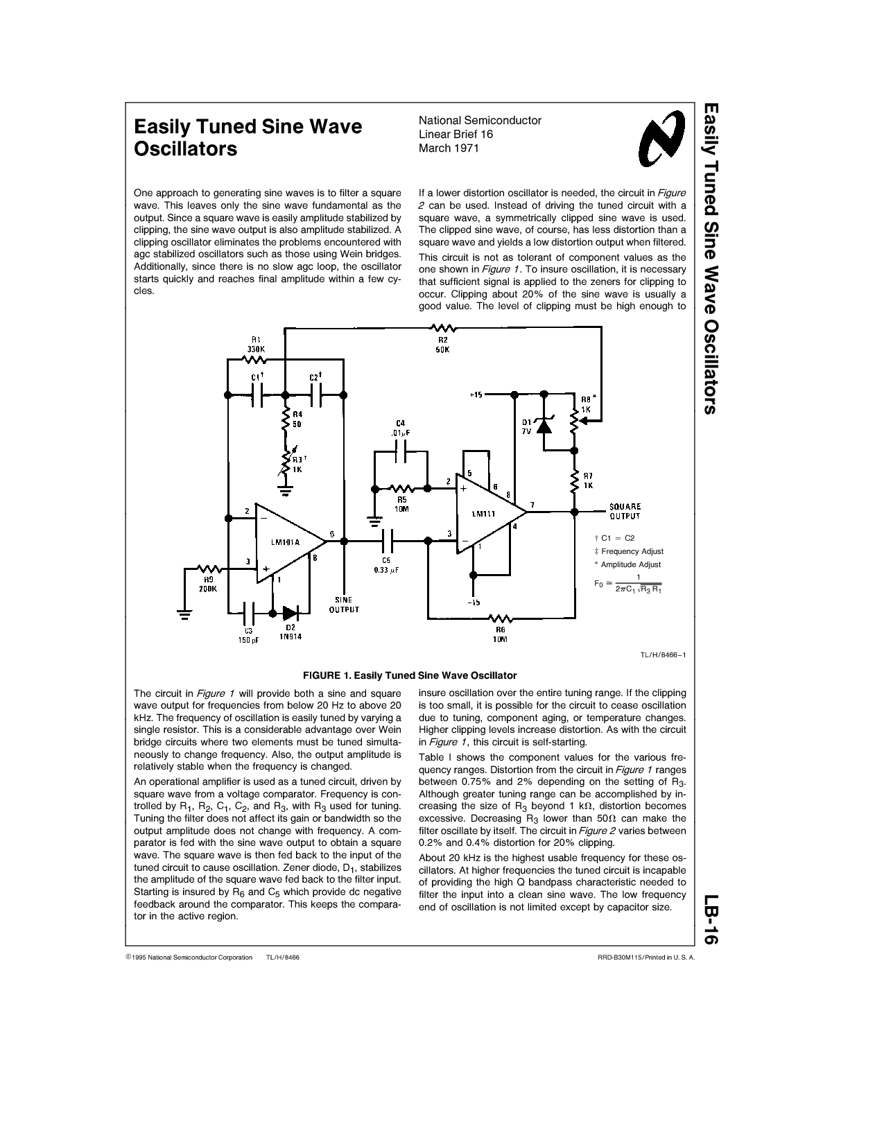
One approach to generating sine waves is to filter a square wave. This leaves only the sine wave fundamental as the output. If a lower distortion oscillator is needed, the circuit in Figure 2 can be used. Instead of...