
HARTLEY OSCILLATOR

The Hartley Oscillator is a type of electronic oscillator that generates sine waves, primarily used in radio frequency applications. It employs a tank circuit composed of an inductor (L) and a capacitor (C) to produce oscillations. The oscillator's operation is based on the feedback principle, where a portion of the output signal is fed back to the input to sustain oscillations.
In a typical Hartley Oscillator configuration, the circuit consists of a bipolar junction transistor (BJT) or field-effect transistor (FET) with the LC tank circuit connected to its collector. The inductor in the tank circuit is often split into two parts, which allows for a tapping point to be established between them. This tapping point is crucial as it provides the necessary feedback signal to the emitter of the transistor.
The base of the transistor is biased with a steady voltage, ensuring that the transistor remains in the active region for amplification. The small feedback signal from the tapping on the inductor is coupled to the emitter, where it influences the transistor's operation, thereby sustaining the oscillation process. The oscillation frequency is determined by the values of the inductance and capacitance in the tank circuit, calculated using the formula:
\[ f = \frac{1}{2\pi\sqrt{LC}} \]
where \( f \) is the frequency of oscillation, \( L \) is the total inductance, and \( C \) is the capacitance.
The Hartley Oscillator is favored for its simplicity and ease of tuning, making it suitable for various applications including signal generation, RF amplification, and as a local oscillator in superheterodyne receivers. Proper design considerations, such as component selection and layout, are essential to ensure stable oscillation and minimize unwanted harmonics.The Hartley Oscillator is characterised by an LC circuit in its collector. The base of the transistor is held steady and a small amount of signal is taken from a tapping on the inductor and fed to the emitter to keep the transistor in oscillation. 🔗 External reference
Related Circuits
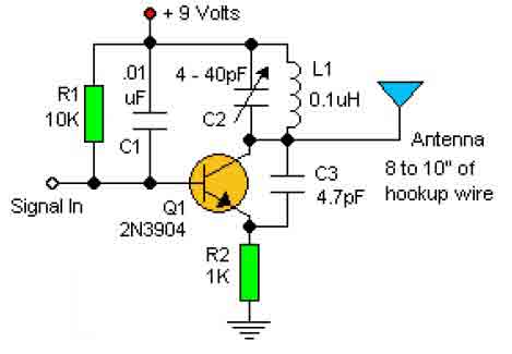
This basic RF oscillator circuit is easy to build and the components are not critical. Most of them can be found in your junk parts box. The L1 antenna coil can be made by close winding 8 to 10...
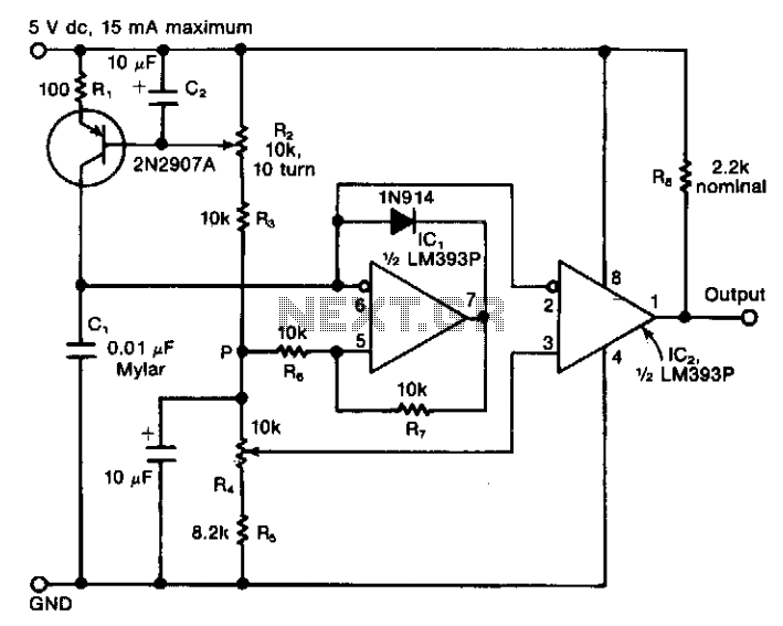
The circuit features a variable current source that charges a capacitor, which is rapidly discharged by a Schmitt-trigger comparator. The resulting sawtooth waveform is provided to another comparator with a variable switching level. The output from this second comparator...
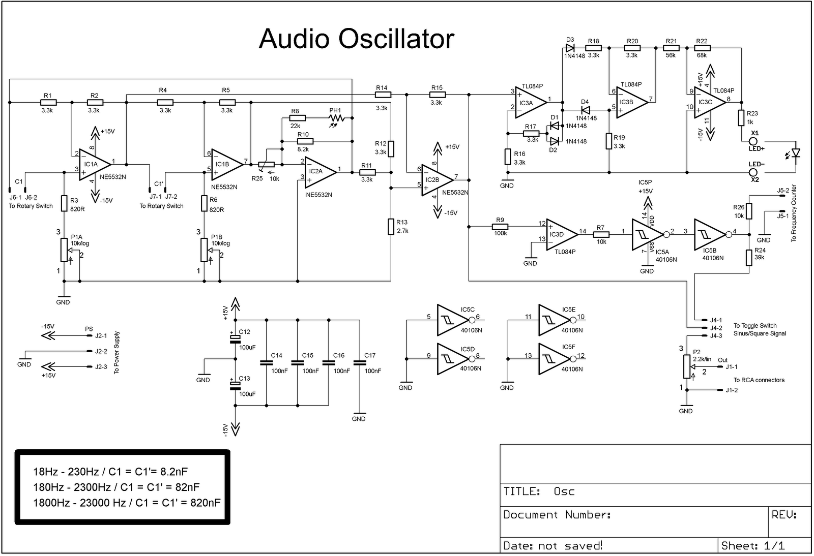
The project involves adding a DIY audio oscillator to a home workshop, which is essential for testing audio projects. While a basic oscillator is already available, it lacks a frequency counter. The design follows a schematic that provides a...
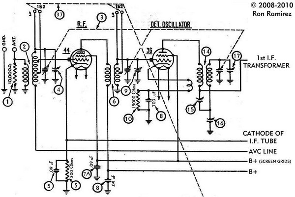
The initial step involves taking notes to indicate which wire connects to each terminal on the 36 tube socket. Remove all wires connected to the 36 tube socket. Next, drill out the rivets that secure the five-pin 36 tube...
The circuit's frequency of oscillation is given by the formula: f = 2.8 / [C1 x (R1 + R2)]. By adjusting the potentiometer R2, the output frequency can be varied from 60 Hz to 20 kHz. A portion of...
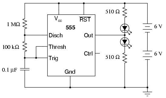
The 555 integrated circuit is a versatile timer that can be used for various applications. This experiment focuses on its operation as an astable multivibrator or oscillator. When connected to a capacitor and two resistors, it generates a square-wave...