
Hartley Oscillator Calculator

The inductive three-point oscillator circuit is a specialized configuration that leverages the characteristics of inductors and capacitors to generate oscillations. The circuit comprises a transistor (Q), two inductors (L1 and L2), and a capacitor (C) that together form a resonant LC circuit. The feedback mechanism is critical for sustaining oscillations; L2 not only participates in the resonant circuit but also acts as a feedback network, providing necessary voltage to the base of the transistor through the coupling capacitor (Cb).
The design allows for the creation of a communication channel, where the resonant circuit connects three distinct endpoints, each associated with a transistor. This arrangement enables efficient signal transmission and amplification, making it suitable for various applications in communication systems.
In terms of performance, the high-Q characteristic of the circuit ensures that the oscillation frequency remains closely aligned with the resonant frequency of the LC circuit. The relationship is defined by the formula governing LC resonant circuits, which indicates the frequency at which the circuit naturally oscillates. However, while the three-point oscillator is adept at initiating oscillations, the output waveform quality can be suboptimal.
This degradation arises from the feedback voltage that is influenced by the inductance at both ends of the inductor. At higher frequencies, the impedance of the inductance increases, which can introduce additional harmonic components into the feedback signal. As a result, the output waveform not only reflects the fundamental frequency but is also populated with high harmonics, which can distort the signal and affect the overall performance of the circuit.
In summary, the inductive three-point oscillator circuit is a complex yet effective design that exemplifies the interplay between inductance, capacitance, and feedback mechanisms in generating oscillations, albeit with certain trade-offs in output waveform fidelity.Q is the transistor, L1, L2, C resonant circuit formed, L2 double as feedback network, through the coupling capacitor Cb will be sent to feedback voltage transistor base. Figure 2 shows the communication channel, resonant circuit with three endpoints and the three most connected transistor, it is known as the inductive three-point oscillator circuit, also known as feedback oscillation circuit inductance.
When a high-Q circuit, the circuit`s oscillation frequency essentially equal to the resonant frequency of LC circuit, the formula is as follows: Inductance characteristics of three-point oscillator circuit is easy to start oscillating, but its output waveform is poor, due to feedback voltage from both ends of the inductor, while the inductance of the high harmonics of the impedance of a larger, and thus contains the feedback voltage more harmonic components, therefore, the output waveform also contains more high harmonics. 🔗 External reference
Related Circuits
An audio test oscillator circuit typically produces a square wave if the oscillation frequency is low enough in relation to the amplifier's bandwidth. This circuit features a crystal-controlled oscillator designed for low-frequency sine wave generation, characterized by low distortion,...
A Colpitts oscillator can be implemented using an operational amplifier, provided that the op-amp has an appropriate bandwidth. An example of such a circuit can utilize the LT1190 or LT1191. The Colpitts oscillator is a type of electronic oscillator that...
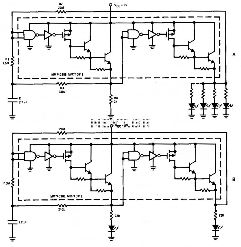
The driver in the package is configured as a Schmitt trigger oscillator (A), utilizing resistors R1 and R2 to create hysteresis. The inverting feedback timing components consist of resistor R3 and capacitor C, while resistor R4 serves as the...
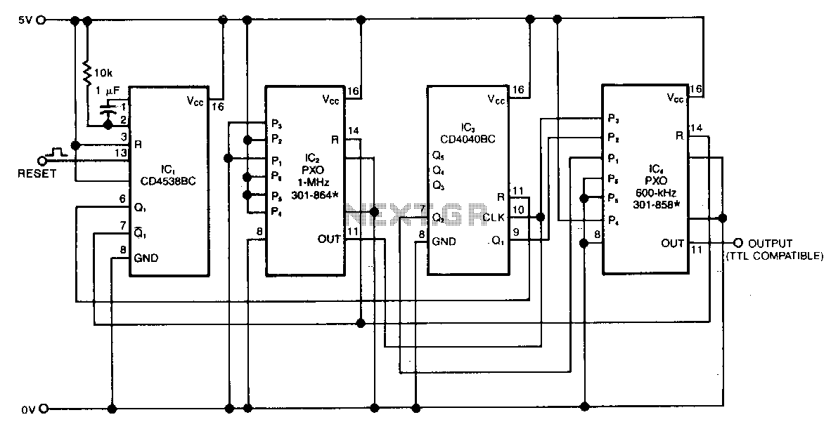
The swept-frequency oscillator provides a cost-effective source of discrete frequencies for testing digital circuits. This configuration generates an 80-second sequence of eight frequencies, with each frequency maintained for 10 seconds. The dwell time and the number of frequencies can...
The oscillator circuit involves two unity gain phase shift stages, A1 and A2, in tandem and a gain stage, A3, with back to back diodes and resistor network providing non-linear negative feedback. At a particular frequency (determined by RT...
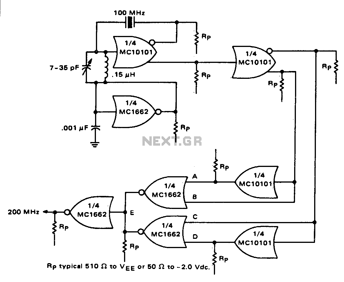
One section of the MC10101 is configured as a 100 MHz crystal oscillator, with the crystal placed in series within the feedback loop. An LC tank circuit is utilized to tune the 100 MHz harmonic of the crystal, which...