
Audio Oscillator schematic

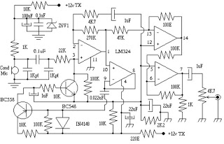
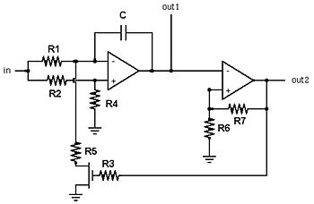
The oscillator circuit described consists of several key components and stages designed to produce a stable sine wave output while minimizing distortion. The circuit begins with two unity gain phase shift stages, labeled A1 and A2, which provide a cumulative phase shift of 180 degrees at a specific frequency determined by the timing components RT and CT. The output from these stages feeds into a gain stage, A3, which is configured with a feedback network comprising back-to-back diodes and resistors. This configuration introduces non-linear negative feedback that stabilizes the output amplitude around 1V RMS, while also allowing for a certain level of harmonic distortion due to the characteristics of the diodes.
The operation of the circuit relies on the principle of phase rotation, where the two phase shift networks ensure the necessary phase conditions for oscillation are met. The inclusion of the final amplifier stage, A4, provides an additional inversion, effectively contributing another 180 degrees of phase shift to the circuit. This design ensures that the overall feedback loop remains positive, thus enabling sustained oscillation.
To manage the amplitude of the output signal and prevent excessive distortion, the circuit employs a limiter, which can be implemented using diodes, thermistors, or other components. However, the design's effectiveness is significantly enhanced by the unique configuration of stage A4, which utilizes a feedforward approach to combine outputs from the previous stages. This method effectively reduces third and higher odd harmonic distortion products that arise from the non-linear feedback mechanism of the diodes.
Despite its simplicity, the circuit does have limitations, particularly in achieving low distortion levels. The use of diodes inherently restricts the distortion to a minimum of approximately 5%, and while alternative components such as thermistors could be used, they do not significantly improve performance compared to a typical Wien bridge oscillator. However, the implementation of stage A4 allows for a substantial reduction of unwanted harmonics, achieving a total harmonic distortion (THD) of only 0.16% at 1kHz, with performance remaining favorable across a range of frequencies.
The oscillator's frequency sweep control is facilitated by a linear potentiometer (RV1A/B), which offers a sweeping range of approximately 24:1, further complemented by a high-low range switch that provides an additional 18:1 ratio. This design allows for comprehensive coverage of the audio frequency range, albeit with some limitations in the lowest octave.
The circuit also features a square/sine wave switch that modifies the feedback configuration around A4. In square wave mode, the op-amp operates in an open-loop condition, resulting in output saturation at the supply voltage limits, thereby generating a square waveform. A diode network is employed to limit the output level during this mode to ensure consistency with the sine wave output.
Powering the oscillator typically involves a nine-volt battery, with the circuit designed to operate effectively across a voltage range from 9.5 volts down to 6.3 volts. The current consumption remains low, with 1.7mA in sine wave mode and 4.7mA in square wave mode, largely due to the use of the TL062 low power dual FET op-amp. Other op-amps, such as the TL072 or TL082, are not recommended for single battery operation due to higher power consumption and lower operational voltage margins. The circuit's power supply configuration includes a voltage divider to create a balanced bipolar supply, enhancing the direct coupling between op-amp stages and minimizing component count while ensuring protection against reverse battery connections.The oscillator circuit (see Figure 1) involves two unity gain phase shift stages, A1 and A2, in tandem and a gain stage, A3, with back to back diodes and resistor network providing non-linear negative feedback. At a particular frequency (determined by RT and CT - the timing components) A1 and A2 provide 90 degrees phase shift each, 180 degrees in total and the circuit begins oscillating, since A3 and its non linear network has more than unity gain for small signals.
As the oscillation level increases the diodes conduct and limit the gain of A3 stabilising the output at the desired level, in this case a little over 1V RMS. However, some distortion of the sine wave peaks is caused by the diodes. The principle is quite simple. Using two phase shift networks, the phase is rotated by 180° at one frequency. The final amplifier provides an additional inversion (effectively 180° phase shift), so the circuit will oscillate. The limiter (whether diodes, thermistor or something else) is used to prevent the amplitude from building up to the point where the signal is grossly distorted.
Normally, diodes are not at all effective in preventing distortion, but that's where the fourth stage comes into its own. The fourth stage, A4, is the real secret of the design since it combines the outputs of the three preceding stages using a feedforward* approach.
This is done in such a way as to reduce the third and higher odd harmonic distortion products generated in those stages due to the back to back diodes used for level stabilisation. Because the diodes are symmetrical in their effect they cause only third and higher odd harmonics of the sine wave output.
The disadvantage of this simple circuit (especially if diodes are used) is that it will be almost impossible to get distortion below around 5% along with reliable oscillation. Even if you can find a suitable thermistor, the distortion will be no better than a typical Wien bridge oscillator, but with more active parts and a restricted frequency range due to the limitations of the opamps.
The net effect of A4 is to remove at least 90% of these unwanted harmonics from the output over the operating range of the oscillator. The prototype measured only 0.16% THD at 1kHz, somewhat less at lower and more at higher frequencies.
At these levels the distortion is barely audible and presents a visually perfect sine wave on an oscilloscope screen. Overall, this represents a much better performance than a typical function generator. he frequency sweep control (RV1A/B, which must be a linear pot) has a range of about 24:1 and in combination with the High-Low range switch having a 18:1 ratio, the audio band is covered (with the exception of the lowest octave) in two overlapping ranges.
The possibility of a single sweep of the audio band without the range switch was tried out and later dropped in preference to the present design. The square/sine wave switch works by disconnecting the negative feedback around A4 allowing the opamp to run "open loop".
In this condition it is overdriven by the oscillator stage causing its output to saturate at the positive and negative supply voltages producing a squared waveform. The additional four diode network which is switched across the output of A4 and voltage limits the output level in square wave mode to match the sine wave level and at the same time regulates against variations in the battery voltage.
The actual operating level of Miniosc is limited by the use of a single nine volt battery if you choose to power it this way. The discharge curves for various types show a voltage variation of from 9.5 volts down to 6.3 volts is to be expected from "fresh" to "flat".
The Miniosc operates as specified over this range with a maximum output level of 1.27 volts RMS sine and 1.45 volts square. The battery drain in sine wave mode is a miniscule 1.7mA increasing to about 4.7mA in square wave mode.
This very low drain is mainly the result of using the Texas Instruments TL062 low power dual FET opamp which is ideally suited to the design. Types like the TL072, TL082 and other dual op-amps with compatible pinouts are not recommended for single 9V battery use due to both the increased battery drain and reduced margin of minimum operating voltage.
The TL062 is alone in having operation specified down to a plus and minus 3 volt supply. Any dual opamp can be used if a pair of 9V batteries are provided, or where the oscillator will be powered from a regulated power supply of 12V or more. One dual opamp that cannot be recommended is the LM358 - it will work, but very badly. Power from the standard 9V 216 style battery feeds a voltage divider (R16 and R17) to provide an artificial centre tap with bypass capacitors and a 1 amp diode to protect the IC from inadvertent reverse connection of the battery.
Even a momentary reversal of a good battery would easily destroy the TL064 IC and any of its relatives. Creating balanced plus and minus 4.5 volt supply rails like this allows direct coupling between all the op-amp stages (including the output level control), and also reduces the number of components.
🔗 External reference
Related Circuits
The TX audio cable can be more complex than the RX audio cable. Typically, the TX audio cable requires a circuit to reduce the voltage from the sound card's LINE OUT jack; otherwise, the radio's transmit circuit may be...
This circuit can be utilized in intercom systems, walkie-talkies, low-power transmitters, and packet radio receivers. Transistors T1 and T2 constitute the microphone preamplifier. Resistor R1 provides the necessary bias for the condenser microphone, while preset VR1 serves as a...
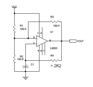
This circuit utilizes the Op-Amp LM301 to generate a simple square wave. The LM301 operates with a power supply range of 3 V to 36 V and can handle a maximum frequency of 325 kHz. The oscillation frequency is...
This sound level meter serves as an excellent one-chip alternative to traditional analog meters. It is entirely solid-state, ensuring durability and longevity. The circuit is based on the LM3915 audio level integrated circuit and requires only a minimal number...
A voltage-controlled oscillator is an oscillator whose frequency of oscillation can be varied by changing an applied voltage. A voltage-controlled oscillator (VCO) is an essential component in various electronic systems, particularly in communication devices, signal processing, and modulation applications. The...
More: The provided input lacks specific details or context regarding an electronic circuit or schematic. To create a comprehensive electronic schematic description, it is essential to include key components, their interconnections, and the overall functionality of the...