
High frequency crystal oscillator

The MC10101 integrated circuit is a versatile component often used in high-frequency applications. In this configuration, it operates as a crystal oscillator, generating a stable frequency output at 100 MHz. The crystal oscillator's feedback loop is critical for maintaining oscillation stability and precision. The inclusion of an LC tank circuit allows for fine-tuning of the oscillator's frequency, ensuring that it aligns perfectly with the desired 100 MHz output.
The buffering section of the MC10101 is essential for isolating the oscillator from subsequent circuitry, preventing loading effects that could alter the oscillation characteristics. This section provides two complementary outputs, which are particularly useful in digital applications where both high and low logic levels are needed simultaneously.
In the frequency doubler configuration, the use of phase shifters is vital for generating the necessary timing relationships between the signals. The two MC10101 gates act as phase shifters, ensuring that the output signals are appropriately delayed to achieve the desired 90° phase difference. This phase shift is crucial for maintaining a 50% duty cycle, which is often required in digital signal applications to ensure proper timing and synchronization.
The additional use of MC1662 NOR gates in this circuit aids in further processing the signals, allowing for the generation of a doubled frequency output while maintaining signal integrity. The design can also accommodate variations in output frequency through the use of delay lines, which can provide precise timing adjustments for applications operating at higher frequencies, such as 200 MHz.
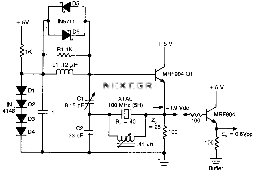
Overall, this circuit configuration showcases the capabilities of the MC10101 and MC1662 components in high-frequency signal generation and manipulation, making it suitable for a wide range of electronic applications that demand precision and reliability.One section of the MC10101 is connected as a 100 MHz crystal oscillator with the crystal in series with the feedback loop. The LC tank circuit tunes the 100 MHz harmonic of the crystal and may be used to calibrate the circuit to the exact frequency.
A second section of the MC10101 buffers the crystal oscillator and gives complementary 100 MHz signals. The frequency doubler consists of two MC10101 gates as phase shifters and two MC1662 NOR gates For a 50% duty cycie at the output, the delay to the true and complement 100 MHz signals should be 90°. This may be built precisely with 2 ns delay lines for the 200 MHz output or approximated by the two MC10101 gates as shown.
Related Circuits
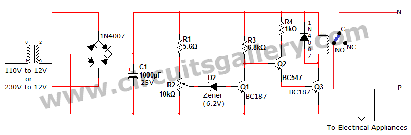
Voltage fluctuation is a significant concern in residential settings. For various reasons, the supply voltage may exceed 110V or 230V. This excessive voltage can potentially damage household electrical devices. An effective solution for electrical protection is the implementation of...
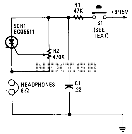
Capacitor C1 charges through resistor R1, and when the gate level established by potentiometer R2 is sufficiently high, the SCR is triggered. Current flows through the SCR and earphones, discharging C1. The anode voltage and current drop to a...
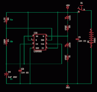
The circuit illustrates a method to obtain a voltage of 90V from a 1.5V battery supply. The LT1073 switching regulator from Linear Technology operates in boost mode and can function with an input voltage as low as 1.0V. The...
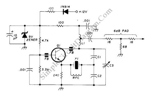
This circuit operates at a frequency range of 90-125 MHz and is particularly useful for VHF/UHF converters. It provides an output power of 5 to 15 mW. The circuit can utilize high-quality fifth- or seventh-over-tone crystal types. A ferrite...
The LM311 is a comparator that operates from a single 5V supply or dual supplies, with an input current of 150 nA and an output drive capability of 50 V and 50 mA. It features a TTL-CMOS compatible output....
This circuit exhibits good performance without an amplifier, having a gain of only one, with built-in parasitics due to the emitter follower negative feedback. Additionally, it serves to stabilize its gain. The circuit under discussion utilizes an emitter follower configuration,...