
Hartley oscillator design with opamp

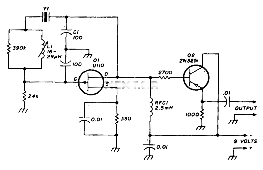
The Hartley oscillator is a type of electronic oscillator that generates sine waves. It typically consists of an operational amplifier (op-amp) configured with a feedback network that includes inductors and capacitors. The fundamental principle behind the Hartley oscillator is the use of a tank circuit, which is formed by the inductors and capacitors, to establish the oscillation frequency.
In a typical op-amp Hartley oscillator, the circuit configuration includes two inductors (L1 and L2) and a capacitor (C) that are arranged to form a resonant LC circuit. The feedback from the tank circuit is fed into the non-inverting input of the op-amp, while the inverting input is connected to a voltage divider to set the gain of the op-amp. The gain must be greater than one for sustained oscillations to occur.
To troubleshoot the lack of oscillation, several factors should be considered. First, ensure that the values of the inductors and capacitors are appropriately selected to achieve the desired oscillation frequency, which can be calculated using the formula:
\[ f = \frac{1}{2\pi\sqrt{L_{total}C}} \]
where \( L_{total} \) is the total inductance of L1 and L2 in series, and C is the capacitance.
Next, verify the op-amp's power supply voltage and ensure it is within the operational range specified in the datasheet. Insufficient power supply levels can prevent the op-amp from functioning correctly.
Additionally, check the connections in the circuit for any loose ends or incorrect wiring, which can significantly affect the performance. The feedback path must be correctly configured to provide the necessary phase shift for oscillation.
It is also important to consider the bandwidth and slew rate of the op-amp being used. An op-amp with inadequate bandwidth or slow slew rate may not be able to produce the fast transitions required for stable oscillation.
Finally, if the simulation environment allows, examine the output waveform characteristics to identify any distortion or clipping that may indicate issues with the op-amp's gain settings or the component values used in the circuit. Adjusting these parameters may help achieve the desired oscillation.Hi! I made an opamp hartley oscillator using a certain electronics simulator and even though simulation takes place I`m unable to get any oscillation.. 🔗 External reference
Related Circuits
Zener diodes were utilized to derive a stabilized voltage for the Hartley oscillator. While sorting through a box of valves, suitable voltage stabilizer valves (CV287) were discovered. During this process, the ECC81 utilized in the local oscillator was noted...
A crystal oscillator, particularly a low-frequency variant, can be effectively constructed using an operational amplifier (op-amp) as the amplification component. Below is the schematic diagram of this circuit. The crystal oscillator circuit utilizes the properties of a quartz crystal to...
An audio test oscillator circuit typically produces a square wave if the oscillation frequency is low enough in relation to the amplifier's bandwidth. This circuit features a crystal-controlled oscillator designed for low-frequency sine wave generation, characterized by low distortion,...
A stable variable crystal oscillator (VXO) utilizing 6- or 8-MHz crystals employs a capacitor and an inductor to facilitate frequency pulling on either side of series resonance. The described circuit operates as a variable crystal oscillator, which is crucial in...
The Oscillator Design Guide is integrated into Agilent EEsof's Advanced Design System environment, functioning as a smart library and interactive handbook for the creation of effective designs. It facilitates quick oscillator design, interactive component characterization, and provides in-depth insights...
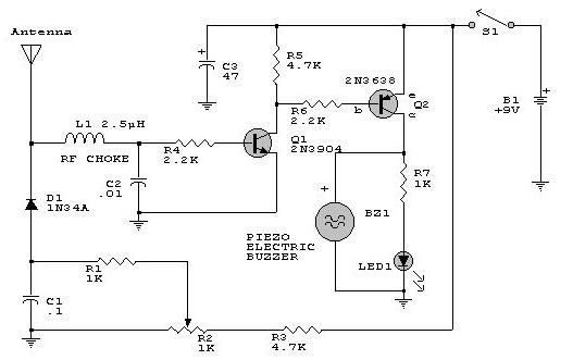
This electronic RF detector project is designed using common transistors and a few standard electronic components. The RF detector responds to RF signals below the standard broadcast band and well over 500 MHz, providing both visual and audible indications...