
Oscillator DesignGuide Reference

The Oscillator Design Guide serves as a comprehensive resource for engineers involved in RF circuit design, particularly in the development of oscillators. It incorporates various oscillator configurations, allowing for flexibility in design and adaptation to specific project requirements. Each oscillator type, including Colpitts, Clapp, Hartley, and their modified counterparts, is constructed with a focus on performance across a designated frequency range, facilitating applications in RF printed circuit boards and microwave systems.
The guide emphasizes the importance of component selection and tuning methods, particularly the usage of variable capacitance tuning ports which enable voltage-controlled oscillator (VCO) designs. The integration of varactor diodes for tuning purposes is a critical feature that enhances the functionality of the oscillators, allowing for precise frequency adjustments. The coupling capacitors play a significant role in determining the coupling strength and tuning range, influencing the oscillator's overall performance.
Moreover, the inclusion of templates and example designs within the ADS environment streamlines the design process, providing a foundation upon which engineers can build and customize their own oscillator circuits. The availability of push-button nonlinear measurements enhances the design experience, offering both novice and expert users valuable insights into the oscillator's behavior under various conditions.
In summary, the Oscillator Design Guide is an essential tool for engineers seeking to design and implement effective oscillator circuits, providing a structured approach to RF design challenges while facilitating a deeper understanding of oscillator functionality and performance characteristics.The Oscillator DesignGuide is integrated into Agilent EEsof`s Advanced Design System environment, working as a smart library and interactive handbook for the creation of useful designs. It allows you to quickly design oscillators, interactively characterize their components, and receive in-depth insight into their operation.
It is easily modifiabl e to user-defined configurations. The first release of this DesignGuide focuses on RF printed circuit boards and microwave oscillations. This document assumes that you are familiar with all of the basic ADS program operations. For additional information, refer to Schematic Capture and Layout. The Oscillator DesignGuide contains templates that can be used in the ADS software environment. It consists of generic colpitts, clapp, modified colpitts, modified clapp, and hartley oscillator design examples, and a library of components and component characterization tools.
The push-button nonlinear measurements are recommended as a starting point for both expert and novice users creating large-signal designs. For the expert, these measurements provide an overview of tool capabilities. For the novice user, they provide a working oscillator together with simulations of its typical characteristics of nonlinear designs.
The full set of available large-signal measurements in the Generic Oscillator example are described in the following table. Subsets of these measurements appear in other examples. Refer to the section Additional Examples The cClappCore. dsn oscillator operates from 0. 5 to 15GHz using the existing component values in the Clapp oscillator sub-circuit. Resonator tank components Ct and Lt are automatically calculated with approximations referenced to 1GHz and displayed on some display pages.
The Ground or Series Resonator port is either connected directly to ground or connected to ground through a series resonator. The Variable Capacitance Tuning Port is used for VCO design by coupling a varactor diode across the tank capacitor Ct.
Coupling is accomplished by capacitor Ccpl. Larger values of Ccpl yield tighter coupling and wider tuning range for a given amount of tuning capacitance variation. The OscPort1 and OscPort2 ports are either connected directly together or connected through a series resonator.
You can connect the OscPort test probe between these two ports for harmonic balance oscillator simulations. The Output Port is used for oscillator signal output. The variable Ctune sets the oscillator at the desired oscillation frequency when the capacitance across the Variable Capacitance Tuning Port is equal to the Ctune set value.
The following image shows an example of the Clapp Oscillator subcircuit. Increase capacitors C1 and C2 for lower frequency oscillator circuits. Adjust resonator frequency offset (currently 390E6) to recenter oscillator frequency. The preceding image shows the cHartleyCore. dsn oscillator core schematic symbol. This oscillator operates from 1 to 1000MHz using the existing component values in the Hartley oscillator sub-circuit. The resonator tank component Ct is scaled from 500MHz with an approximation and displayed on some display pages.
You can connect the Ground or Series Resonator to the port directly to ground, or it can be connected to ground through a series resonator. The Variable Capacitance Tuning Port is used for VCO design by coupling a varactor diode across the tank capacitor Ct.
Coupling is accomplished by capacitor Ccpl. Larger values of Ccpl yield tighter coupling and wider tuning range for a given amount of tuning capacitance variation. The OscPort1 and OscPort2 ports are either connected directly together or connected through a series resonator.
For harmonic balance oscillator simulations, connect the OscPort test probe between these two ports. The Output Port is used for oscillator signal output. The variable Ctune sets the oscillator at the desired oscillation frequency when the capacitance across the Variable Capacitance Tuning Port is equal to the Ctune set value. The following image shows the Hartley Oscillator subcircuit. Increase inductors L1 and L2 for lower frequency oscillator circuits. Adjust resonator capacitor Ct reference value (currently 21. 3pF) to recenter oscillator frequency. The preceding image shows the cModifiedClappCore. dsn oscillator core schematic symbol. The cModifiedClappCore. dsn oscillator operates from 0. 7 to 7. 2GHz using the existing component values in the Modified Clapp oscillator sub-circuit. Resonator tank components Ct and Lt are automatically calculated with approximations referenced to 1GHz and displayed on some display pages.
The Ground or Series Resonator port can be connected directly to ground or connected to ground through a series resonator. The Variable Capacitance Tuning Port is used for VCO design by coupling a varactor diode across the tank capacitor Ct.
Coupling is accomplished by capacitor Ccpl. Larger values of Ccpl yield tighter coupling and wider tuning range for a given amount of tuning capacitance variation. The OscPort1 and OscPort2 ports are either connected directly together or connected through a series resonator.
You can connect the OscPort test probe between these two ports for harmonic balance oscillator simulations. The Output Port is used for oscillator signal output. Variable Ctune sets the oscillator at the desired oscillation frequency when the capacitance across the Variable Capacitance Tuning Port is equal to the Ctune set value.
The following image shows the Modified Clapp Oscillator subcircuit. Increase capacitors C1 and C2 for lower frequency oscillator circuits. Adjust resonator frequency offset (currently 290E6) to recenter oscillator frequency. The preceding image shows the cModifiedColpittsCore. dsn oscillator core schematic symbol. This oscillator operates from 0. 8 to 6. 5GHz using the existing component values in the Modified Colpitts oscillator sub-circuit. Resonator tank inductor Lt is automatically calculated with an approximation and displayed on some display pages. The Ground or Series Resonator port can be connected directly to ground or connected to ground through a series resonator.
The Variable Capacitance Tuning Port is used for VCO design by coupling a varactor diode across the tank inductor Lt. Coupling is accomplished by capacitor Ccpl. Larger values of Ccpl yield tighter coupling and wider tuning range for a given amount of tuning capacitance variation.
The OscPort1 and OscPort2 ports are either connected directly together or connected through a series resonator. Connect the OscPort test probe between these two ports for harmonic balance oscillator simulations. The Output Port is used for oscillator signal output. The variable Ctune sets the oscillator at the desired oscillation frequency when the capacitance resonator .
🔗 External reference
Related Circuits
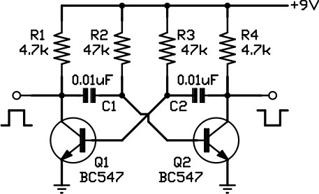
This circuit is one of the simplest to implement but can be challenging to comprehend. It consists of a two-transistor oscillator known as an astable multivibrator, which generates a square wave output that is out of phase. Initially, it...
The oscillator circuit involves two unity gain phase shift stages, A1 and A2, in tandem and a gain stage, A3, with back to back diodes and resistor network providing non-linear negative feedback. At a particular frequency (determined by RT...
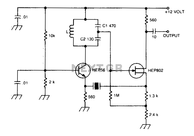
A typical Butler oscillator operating within the frequency range of 20 to 100 MHz incorporates a Field Effect Transistor (FET) in the second stage of its configuration. The circuit exhibits reliability issues when utilizing two bipolar transistors. In some...
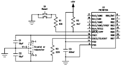
The following file contains detailed information about the design of a basic clock oscillator circuit diagram. Included in this file is information about selecting the components. The clock oscillator circuit is a fundamental component in various electronic systems, providing a...
The variations, which effectively form an alternating signal, will be transmitted through the coupling capacitor to the subsequent stage, indicated by the arrow to the right. One variable resistor can be substituted with another. R1 can be replaced with...
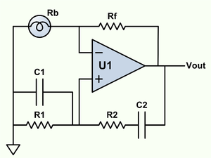
Wien bridge oscillator. A phase-shift feedback oscillator that uses a Wien bridge as the basis for its operation. The Wien bridge oscillator is a type of electronic oscillator that generates sine waves. It operates based on the principle of phase...