
Has 50 times the pre-amplified bridge circuit diagram XTR106

The XTR106 is a precision current source designed for use in applications requiring accurate measurements from resistive bridge sensors, such as strain gauges or pressure sensors. The internal voltage sources of 2.5V and 5V allow for flexible excitation of various bridge configurations, enhancing the device's versatility. The ability to operate effectively with low-resistance bridges is particularly beneficial in applications where sensor resistance may be less than 1kΩ.
To ensure stable operation and accurate readings, a series resistance of 3.4kΩ is included in the circuit to limit the excitation current to a safe 2.5mA. This configuration prevents excessive heating and potential damage to the bridge sensor, preserving its integrity over time.
The dual OPA2277 operational amplifiers are utilized to amplify the output signal from the bridge. These amplifiers are selected for their low offset voltage and drift characteristics, which are critical for maintaining measurement accuracy in precision applications. By compensating for the reduced output from the bridge, the OPA2277 amplifiers enhance the signal-to-noise ratio, allowing for reliable data acquisition.
The circuit also addresses the nonlinearity of the bridge output. The total current, ITOTAL, is calculated as the sum of individual currents flowing through the circuit, specifically 0.7mA, 1.6mA, and 2.5mA. This current summation is crucial for understanding the overall performance of the system and ensuring that the bridge operates within its specified parameters.
In summary, the XTR106, in conjunction with the OPA2277 amplifiers, provides a robust solution for interfacing with low-resistance bridge sensors, ensuring accurate, stable, and reliable measurements in various electronic applications. As shown in FIG, XTR106 has two internal source voltage (2.5V and 5V) to provide incentives, and therefore can be adapted to a wide range of values of the bridge, without addit ional circuitry can be lower than the resistance of 1k bridge work. When XTR106 for low resistance bridge, the bridge across the series resistance in (3.4k ) to limit the excitation current ( 2.5mA). Dual OPA2277 op amp up the amplifier as a preamplifier to compensate for reduced output of the bridge, while reducing offset voltage and drift.
The figure is positive correction bridge nonlinear, ITOTAL 0.7mA + 1.6mA 2.5mA.
Related Circuits
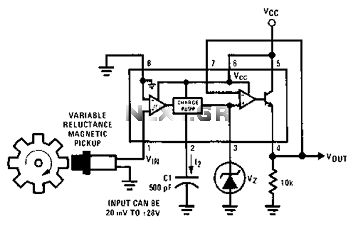
After each zero electromagnetic pickup receives a sine wave input, as illustrated in the National Semiconductor LM2907 circuit, it generates an output pulse. This circuit can be utilized in digital control systems. The width of each pulse corresponds to...
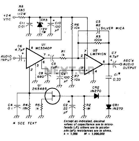
An audio signal applied to the input VI is passed through the operational amplifier 741, designated as U2. After amplification, the output signal V2 is sampled and sent to a negative voltage doubler/rectifier circuit composed of diodes CR1 and...
Most of the power supply failure indicator circuits need a separate power supply for themselves. But the alarm circuit presented here needs no additional supply source. It employs an electrolytic capacitor to store adequate charge, to feed power to...
This simple circuit tests speakers, microphones, transformers, and voltage. It is essentially a very low-frequency oscillator that produces extremely short pulses. The sound produced is easy to hear and helps determine the precise direction it originates from, making it...
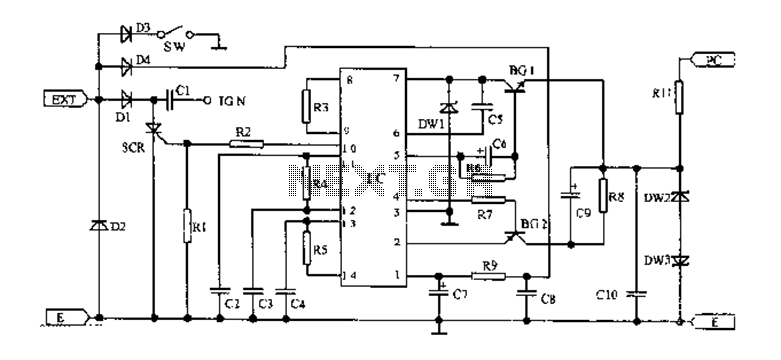
An AC magneto is connected to an external circuit. The output is rectified by diode D1 and stored in capacitor C1. Additional rectification is performed by diodes D4, along with resistors R9 and capacitors C7 and C8, which filter...
The layout design of the TIQ Flash ADC closely follows the provided circuit diagram. A row layout is implemented, with rows stacked on top of each other. Each row comprises a comparator, a gain booster, a 0-1 generator, and...