
Having a differential amplifier and overcurrent protection for power supply circuit 2

The current protection circuit employs a series of transistors and resistors to safeguard against overcurrent conditions. Transistor VTa acts as the primary control element, while VT4 serves to regulate the output voltage. The sense resistor Ro is critical for detecting current levels; when the current exceeds a predetermined threshold, it triggers the protective measures.
In the event of an overcurrent or short-circuit, the circuit enters a fault state where VT3 remains non-conductive, preventing the output voltage from rising above zero. This state effectively disables the power supply to protect downstream components from damage. To restore functionality, the circuit must be reset. This can be achieved either by manually re-closing the circuit or by integrating a reset button in the collector path of VTa, allowing for a controlled restart.
Capacitor Cz plays a vital role in managing the timing of the circuit's response to power restoration. Upon re-energization, Cz delays the activation of the output voltage until the system is stable, ensuring that VT4 is properly activated to provide the necessary voltage. The resistor Rs is essential for setting the correct bias point for VTi, enabling reliable operation of the circuit under normal conditions.
This design illustrates a robust approach to current protection, combining active and passive components to ensure safe operation in the presence of fault conditions. The careful selection of component values and configurations is crucial for achieving the desired performance and reliability in various applications. By the transistor VTa, VT4, sense resistor Ro-current protection circuit and other components. The power supply after overcurrent or short-circuit fault is eliminated, can not resume normal operation (because VT3 conduction condition has not changed, the output voltage is still zero). To reset, you must re-closing or series in the collector circuit VTa a reset button for the job. Now the capacitor Cz from closing when the power delay action to ensure that the pilot through VT4, in order to establish the output voltage; electrical resistance Rs of the role of the regulator is to ensure that there is an appropriate VTi hope bias.
Related Circuits
This circuit utilizes a 13-volt zener diode (D2) for voltage regulation. Approximately 0.7 volts are dropped across the base-emitter junction of the transistors, resulting in a higher current output of 12.3 volts. The circuit is capable of supplying loads...
A 2 µF capacitor is charged to approximately 340 volts, and the discharge is controlled by a silicon-controlled rectifier (SCR). A Schmitt trigger oscillator (74C14) and a MOSFET (IRF510) are utilized to drive the low-voltage side of a small...

The thermostat electric circuit operates as depicted in the figure. It has three settings: off, low power (Lo), and high power (Peru HL). When the DIP switch SA is set to the Lo position, 220V AC is directed through...
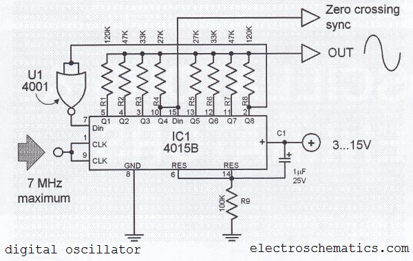
The digital sine wave generator (oscillator) circuit requires only a few components to produce signals with high amplitude constants and a wide range of variable frequencies. This circuit generates a sine wave signal, and by altering the values of...
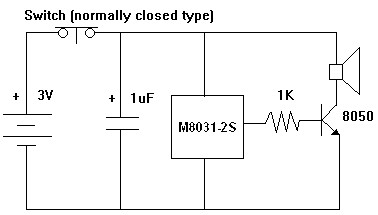
The M8031 circuit features an integrated RC oscillator and digital envelope circuits, which minimize the need for external components. It produces a sound that mimics a mechanical ding-dong. The M8031 operates with a low input voltage range of 1.3...
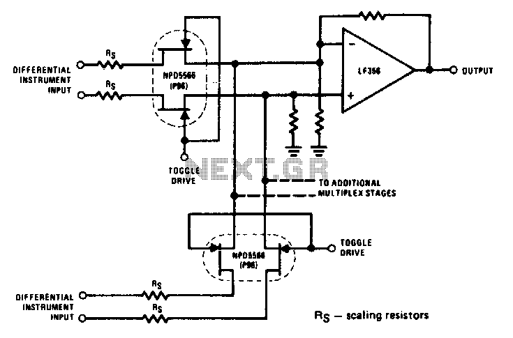
The NPD5566 monolithic dual is utilized in differential multiplex applications where the Rds(ON) should be closely matched. The monolithic dual tracks at better than ±1% over a wide temperature range of -25°C to +125°C, making it an unusual yet...