
Head light timer circuit

The timer circuit for car headlights employs a straightforward yet effective design that integrates discrete components to manage the lighting duration. The circuit begins with a power source, typically the vehicle's battery, supplying voltage to the system. The push button switch P1 serves as a manual trigger. Upon activation, it allows current to flow into the capacitor C1, initiating its charging process. The choice of C1's capacitance value is crucial, as it directly influences the timing characteristics of the circuit.
Transistor Q1 operates as a switch, controlling the flow of current to the next stage. When C1 reaches the battery voltage, Q1 turns on, creating a path for current to flow to transistor Q2. The activation of Q2 subsequently energizes relay K1, which is responsible for connecting the headlights to the power supply, thereby illuminating them.
The relay is an electromechanical switch that maintains its state while C1 discharges through resistor R1. The discharge rate, determined by the RC time constant (τ = R1 * C1), dictates how long the headlights remain on. For a delay of 1.5 minutes, appropriate values for R1 and C1 must be selected, ensuring that the circuit functions effectively within the desired time frame.
Once the capacitor C1 discharges below a certain threshold, transistor Q1 turns off, which in turn deactivates Q2 and opens the relay K1, cutting off power to the headlights. This automatic shut-off feature is particularly beneficial for preventing battery drain when the vehicle is parked in low-light conditions.
Overall, this compact timer circuit enhances vehicle functionality by providing convenience and ensuring that headlights are not left on inadvertently, thus contributing to a more user-friendly driving experience.This circuit is a compact timer circuit that will keep the headlights of your car ON for about 1. 5 minutes and then turns it OFF. This circuit incorporated to your car will help you to access dark places with out the need to come back and turn OFF the head lights. When the push button switch P1 is pressed the capacitor C1 is charged to the full bat tery voltage. As a result the transistor Q1 is turned ON, which in turns ON Q2 which in turns drives the relay K1 to glow the head lights. The relay K1 will remain activated until the capacitor C1 is fully discharged. The time delay of the circuit depends on values of C1 & R1 and here it is set to be 1. 5 minutes. We aim to transmit more information by carrying articles. Please send us an E-mail to wanghuali@hqew. net within 15 days if we are involved in the problems of article content, copyright or other problems.
We will delete it soon. 🔗 External reference
Related Circuits
The schematic presented here can be utilized as a circuit for a car brake light or headlight flasher, designed to flash two 10-watt, 12-volt lamps in a car or any vehicle. This circuit employs a simple flashing mechanism suitable for...
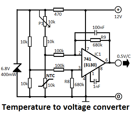
This simple temperature-to-voltage converter circuit allows for precise measurement of room temperature using an NTC resistor or thermistor. The temperature-to-voltage converter circuit typically employs a negative temperature coefficient (NTC) thermistor, which exhibits a decrease in resistance as temperature increases. This...

This circuit represents a remote control unit that utilizes radio frequency signals to operate various electrical appliances. The remote control unit features four channels, which can be expanded to twelve. This circuit stands out from similar designs due to...
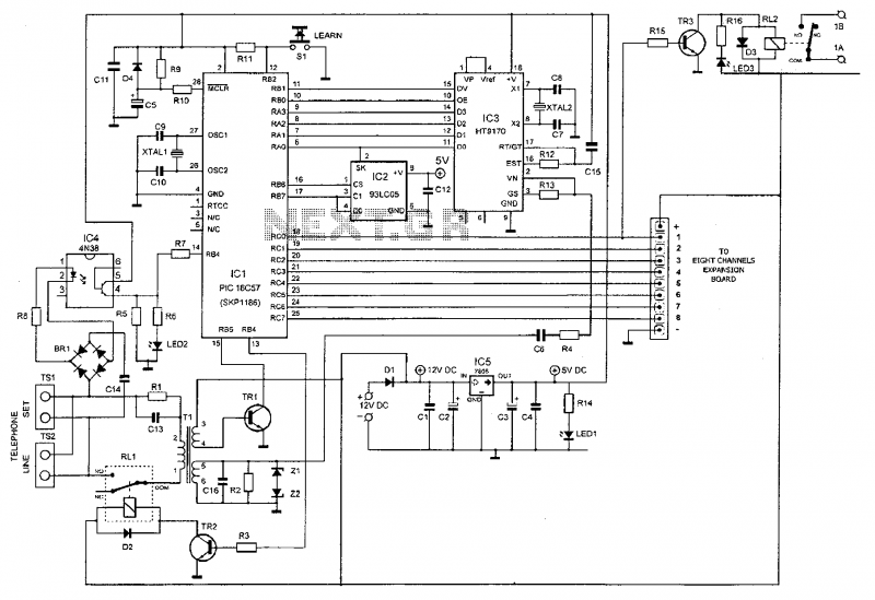
This device enables remote control of various appliances (up to eight with suitable add-on expansion boards) such as lights, water heaters, air conditioning, plant watering systems, alarms, etc., via a relay. It allows users to perform actions such as...
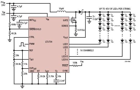
The LT3754 is a 16-channel LED driver featuring a step-up DC-DC controller developed by Linear Technology. It is designed to drive LEDs with a voltage of up to 45V. Each channel of the LT3754 LED driver is equipped with...
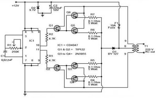
A 12 V car battery can be utilized as the 12 V input power source. The potentiometer R1 can be adjusted to achieve a 50 Hz output frequency. It is recommended to use a 10 A fuse in series...