
headphone amplifier class a

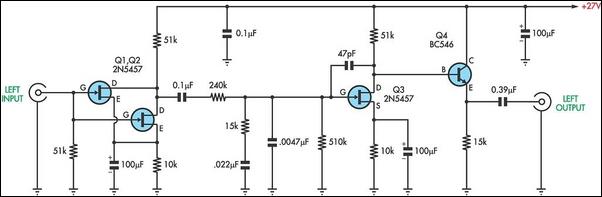
The described circuit is a basic signal processing circuit designed to handle audio or low-frequency signals while maintaining fidelity in terms of distortion and frequency response. The input resistance of 250K ohms indicates it is suitable for interfacing with high-impedance sources, ensuring minimal loading effect on the preceding stage. This high input resistance is advantageous in applications such as audio preamplifiers or sensor interfaces, where preserving the integrity of the original signal is critical.
The circuit is capable of driving loads ranging from 100 ohms to 2K ohms, making it versatile for various applications. The lower end of the load range (100 ohms) suggests it can interface with low-impedance devices, such as speakers or certain types of sensors, while the upper limit of 2K ohms allows compatibility with higher impedance loads, such as line-level inputs on mixers or amplifiers.
In terms of performance, the circuit is designed to minimize distortion across the frequency spectrum, which is crucial for applications in audio processing. The frequency response should be flat over the intended operating range, ensuring that all frequencies are amplified equally without coloration. This characteristic is essential for maintaining the quality of audio signals, making the circuit suitable for professional audio equipment.
Overall, this circuit represents a fundamental building block in electronic design, emphasizing the importance of input impedance, load driving capability, and fidelity in frequency response and distortion.Even if simple the circuit, plirej` all condition, regarding the distortion and the response of frequency. The resistance of entry is 250K and the load that can drive is between 100R and 2K.. 🔗 External reference
Related Circuits
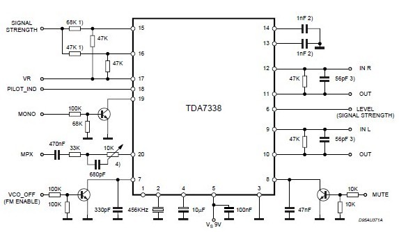
An FM stereo decoder can be designed using the TDA7388A, which features a compact design. This FM stereo decoder schematic circuit utilizes the TDA7388 integrated circuit, produced by ST Microelectronics. The TDA7388 is a monolithic integrated stereo decoder equipped...
Stereo tube amplifier circuit built with 5 power tubes: 6SQ7-GT, 6V6-GT, and 5Y3-GT. This circuit generates up to 4 watts of audio output per channel. The stereo tube amplifier circuit utilizes a combination of five power tubes, specifically the 6SQ7-GT,...
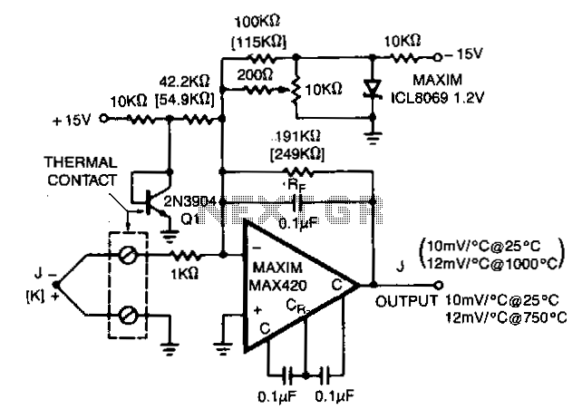
The MAX420 is operated at a gain of 191 to convert the 52 µV/°C output of the type J thermocouple to a 10 mV/°C signal. The -2.2 mV/°C temperature coefficient of the 2N3904 is added into the summing junction...
There are two types of preamplifiers for magnetic phono cartridges. The most common type includes an RIAA equalization network in the feedback loop, as described in the March 2002 issue of SILICON CHIP. The second type, previously used in...
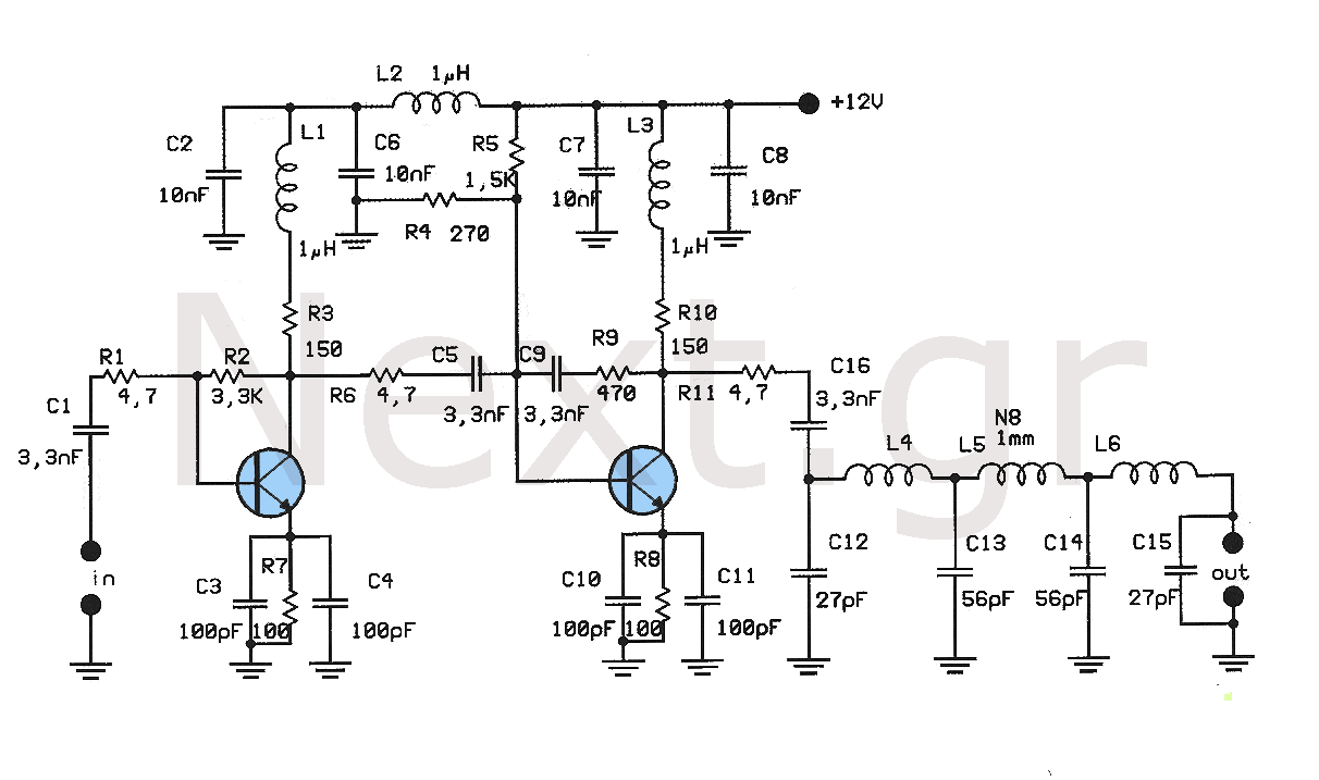
This amplifier is designed to amplify low-level signals from oscillators in the FM band. It lacks frequency regulators with variable capacitors and coils, providing a wide range and moderate power suitable for driving multiple linear amplifiers. The construction utilizes...

The 60-watt linear amplifier is a straightforward all-solid-state circuit utilizing the power MOSFET IRF840. The IRF series of power transistors is available in various voltage and power ratings, with a single IRF840 capable of handling a maximum power output...