
60W Linear amplifier

The 60-watt linear amplifier circuit is designed for efficient operation and reliability, leveraging the capabilities of the IRF840 MOSFET. The IRF840 is notable for its high power handling capabilities, making it suitable for applications requiring significant output power. The amplifier circuit is characterized by its simplicity, ensuring ease of assembly and alignment. The recommended dummy loads, such as the 24V 6-watt bulb or the 230V 60-watt bulb, provide flexibility in testing and tuning the amplifier's performance.
In terms of circuit design, the use of a 10K preset resistor for adjusting the drain current is crucial for optimizing performance. This adjustment allows for fine-tuning of the MOSFET's operating point, ensuring that it operates within safe limits while delivering the desired output power. The chosen gate voltage of 0.8V is critical in preventing potential damage due to self-oscillation, a phenomenon that can occur if the gate voltage exceeds safe thresholds.
The construction details, such as the coil on the drain and the RFC, are essential for maintaining stability and efficiency in the circuit. The specific winding configurations on the toroids are designed to minimize losses and ensure proper impedance matching. The use of stacked toroids to form a balun core is a practical approach to achieving the required inductance while maintaining a compact form factor.
Overall, the 60-watt linear amplifier represents a robust solution for applications requiring solid-state amplification, with considerations for component selection, layout, and thermal management ensuring reliable operation in various conditions.The 60 Watt linear amplifier is simple all solid state circuit using power mosfet IRF840. The IRF series of power transistors are available in various voltage and power ratings. A single IRF840 can handle maximum power output of 125 watts. Since these transistors are used in inverters and smps they are easily available for around Rs: 20/-. The IRF linear amplifier can be connected to the out put of popular VWN-QRP to get an output of 60 Watts. The circuit draws 700 ma at 60 Volt Vcc. Good heat sink is a must for the power transistor. Alignment of the circuit is very easy. Connect a dummy load to the out put of the circuit. You can use some small bulb like 24V 6Watts as the dummy load. I have even used 230V 60Watts bulb as dummy load with my IRF840 power amplifier working at 120Volts. Adjust the 10K preset to get around 100 ma Drain current. I used gate voltage of 0. 8V with my linear amplifier. A heigh gate voltage can make the power transistor get distroyed by self oscillation. So gate voltage must be below 2V and fixing at 1V will be safe. The coil on the drain of IRF is 3 turns 20 SWG wound on 4 number of T13. 9 torroids (two torroids are stacked to form a balun core). The RFC at the Vcc line is 20 Turns 20 SWG wound on T20 torroid. 🔗 External reference
Related Circuits
All ground points in the circuit should be connected to a single point and grounded if possible, or connected to the transformer's 0V marked wire as shown in the circuit. In electronic circuit design, proper grounding is crucial for maintaining...

This is a low watt audio amplifier with a different technique in design. The 1.8K resistor has been connected to output of the circuit instead of VCC line. The output power of the circuit is about 250mW on an...
At some stage, we will all find ourselves pushing hi-fi equipment just a little too hard, and if lucky, will just find that the sound has become "dirty". If this happens too often or is too severe, tweeters are...
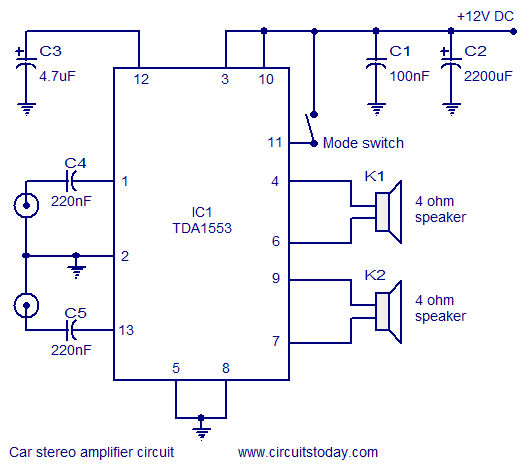
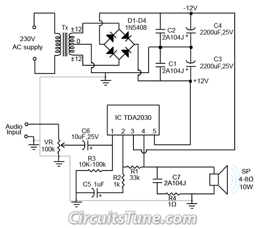
A car stereo amplifier circuit that can be used in automobiles, designed using the Class-B audio amplifier TDA1553, complete with a circuit diagram and schematics. The car stereo amplifier circuit utilizes the TDA1553, a Class-B audio amplifier known for its...
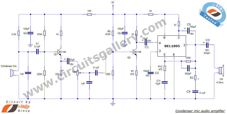
This document presents an audio amplifier circuit suitable for use in walkie-talkies, low-power transmitters, and packet radio receivers. The circuit utilizes a condenser microphone audio amplifier that delivers high-quality audio output of 0.5 watts at 3 volts. The design...
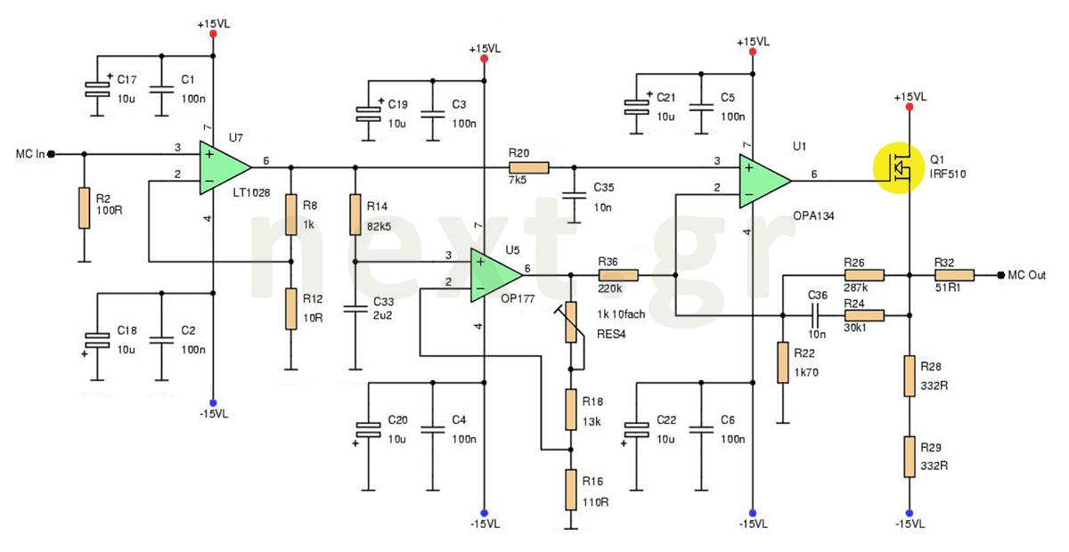
This microphone preamplifier circuit enhances the acoustic signal of a moving coil microphone (MC) with a sensitivity of 150μV at line level. In this design, a specific technique is not employed because the noise produced does not significantly impact...