
Stereo Tube Amplifier 4 Watts

The stereo tube amplifier circuit utilizes a combination of five power tubes, specifically the 6SQ7-GT, 6V6-GT, and 5Y3-GT, to achieve a warm and rich audio output. The 6SQ7-GT serves primarily as a dual triode amplifier, responsible for signal amplification and phase splitting. This tube is crucial for ensuring that the audio signal maintains clarity and fidelity during the amplification process.
The 6V6-GT power tubes are employed in the output stage of the amplifier. Known for their excellent linearity and low distortion characteristics, these tubes are capable of delivering up to 4 watts of output power per channel. This output is suitable for driving small to medium-sized speakers, providing a classic tube sound that is often described as smooth and musical.
The 5Y3-GT tube functions as the rectifier in the power supply section of the amplifier. It converts the alternating current (AC) from the power transformer into direct current (DC), which is necessary for the operation of the amplifier's circuit. The 5Y3-GT is renowned for its ability to produce a soft start-up characteristic, which helps to prolong the lifespan of the other tubes in the circuit.
The overall design of the amplifier circuit is likely to include a power transformer, output transformers, coupling capacitors, and various resistors to set the biasing and gain levels. Properly designed, the circuit will ensure that the audio output maintains a high signal-to-noise ratio and minimal distortion, resulting in an enjoyable listening experience.
This stereo tube amplifier circuit exemplifies the classic approach to audio amplification, combining vintage tube technology with modern design principles to deliver quality sound reproduction.Stereo tube amplifier circuit which is built based 5 power tubes of 6SQ7-GT, 6V6-GT and 5Y3-GT. This circuit generates up to 4 watts audio output each channel 🔗 External reference
Related Circuits
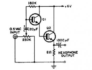
This schematic diagram illustrates a simple headphone amplifier circuit constructed using two NPN transistors. Suitable transistor options include the BC549C, as well as other NPN transistors such as the European equivalents BC548C, BC547C, BC239, 2N5818, or 2N2222. An audio...
This microphone preamplifier utilizes the low-noise integrated circuit (IC) uA739. It serves as a practical example of designing an effective preamplifier for dynamic microphones. The IC contains two identical integrated preamplifier circuits, with the second preamp functioning in the...
The TMB-1 is an RF amplifier unit and receiving accessory compatible with low-impedance broadband loops, high-impedance terminated loops (such as Pennant, Flag, or Kaz Delta), and whip (telescoping rod) antennas. This design is optimized for operation within the frequency...
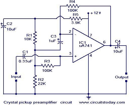
A preamplifier that operates on a single supply and is suitable for high-impedance crystal pickups is presented here. The circuit functions as a non-inverting AC amplifier, with the gain determined by the feedback resistor R4; a smaller R4 results...
Both parts of the circuit are biased with the constant current sources as shown, and the signal from the collector of the PNP is followed by the Darlington class A output stage whose idle current is controlled by the...

A simple transistor amplifier circuit diagram and schematic that can be used as a 12-watt audio transistor amplifier. An operational amplifier (op-amp) integrated circuit (IC) is used to produce the required gain. This circuit is designed to amplify audio signals,...