Headphone Amplifiers

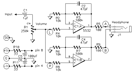
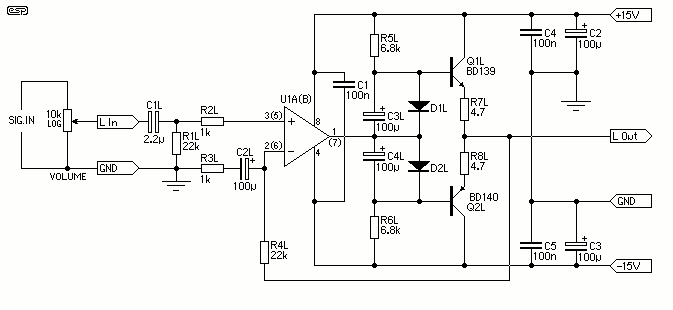
High-quality amplifier for headphones electronics project. No need for preamplifier. Circuit diagram.
The proposed circuit features a high-quality headphone amplifier designed to enhance audio signals for personal listening devices. This amplifier eliminates the requirement for a preamplifier, allowing for a more streamlined and efficient design. The circuit is tailored to deliver optimal sound quality while maintaining a compact size, suitable for various applications, including portable audio devices and home audio systems.
The core of the amplifier circuit typically consists of operational amplifiers (op-amps) configured in a non-inverting amplifier setup, which provides high input impedance and low output impedance. This configuration minimizes signal loss and ensures that the headphones receive a clean, amplified signal. The choice of op-amps is crucial, as high-performance audio op-amps can significantly enhance the overall audio fidelity.
Power supply considerations are also essential in this design. A dual power supply is often utilized to provide both positive and negative voltage rails, which allows for a wider dynamic range and improved linearity in the output signal. Additionally, decoupling capacitors should be placed close to the op-amps to filter out any power supply noise that could affect audio quality.
Feedback resistors are selected to set the desired gain of the amplifier, typically ranging from 2 to 10, depending on the specific headphones being used. A volume control potentiometer can be integrated into the circuit to allow users to adjust the output level conveniently.
Furthermore, protection features such as output capacitors may be included to prevent DC offset from reaching the headphones, which could potentially cause damage. The circuit diagram should clearly illustrate the connections between components, including the input jack, output jack, op-amps, resistors, capacitors, and power supply connections.
Overall, this headphone amplifier circuit is designed to provide high-quality audio performance while being user-friendly and adaptable to various headphone types. Proper layout and component selection will ensure that the amplifier meets the expectations for audio clarity and performance.high quality amplifier for headphones electronics project. no need for preamplifier. circuit diagram.. 🔗 External reference
