
Infrared headphones transmitter circuit

The infrared headphone transmitter circuit operates by utilizing three infrared LEDs (IR LEDs) to create an optical link that transmits audio signals wirelessly to compatible headphones. The power supply for the circuit is set at 9V, which is a common voltage level for such devices, ensuring adequate performance and efficiency.
The current flowing through the infrared LEDs is controlled by a transistor, labeled as T1 in the schematic. This transistor acts as a switch or amplifier, allowing for the modulation of the current based on the input audio signal. The adjustment of the current level is facilitated by a potentiometer, denoted as P1, which provides the user with the ability to fine-tune the brightness of the infrared LEDs. This adjustment is crucial, as it can help to optimize the transmission range and ensure that the signal is strong enough to be received by the headphones without distortion.
The total current consumption of the infrared transmitter is approximately 60mA when operating at 9V. This level of current consumption is efficient for battery-operated devices, allowing for extended usage time without frequent recharging or battery replacement.
To enhance the performance of the transmitter, additional components such as capacitors and resistors may be integrated into the circuit design. Capacitors can be used for filtering and stabilizing the power supply, while resistors can help to limit the current flowing through the LEDs, preventing damage and ensuring longevity.
The overall design of the circuit must also consider factors such as heat dissipation, component ratings, and layout to minimize electromagnetic interference, which can degrade the quality of the audio signal being transmitted. Proper shielding and placement of the components can further enhance the reliability and performance of the infrared headphone transmitter.The transmitter offers a optical link (infrared) for headphones. Three infrared leds (ir) are polirised by T1 current, P1 is used to adjust the current level. Current consumption of this headphones infrared transmitter is about 60mA at 9V.. 🔗 External reference
Related Circuits
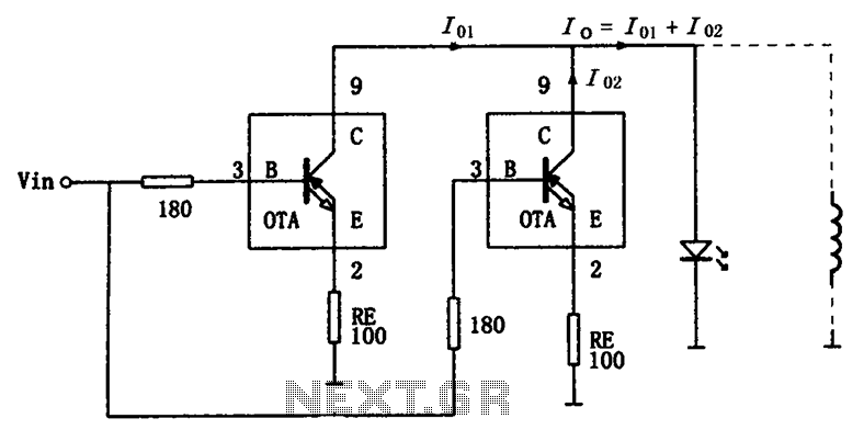
The high-speed parallel current drive circuit utilizes the OPA660 operational transconductance amplifier (OTA). An input signal, Vin, is connected to a 180-ohm resistor equivalent device at the base (pin 3) of the OPA660. The collector (pin 8) is directly...
In the image above, Oscium's iMSO-104 oscilloscope is measuring the output waveform of an infrared receiver (IR Rx). The iPad and iMSO serve as the oscilloscope to measure the receiver's output signal as the alignment between the transmitter and...
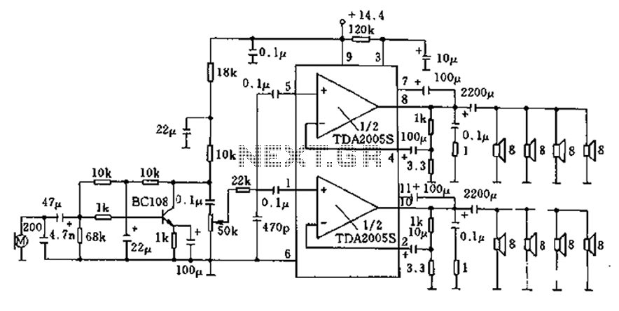
20W bus radio and megaphone circuit utilizing the TDA2005S double low-frequency power amplifier integrated circuit design. The front end can be connected to either a microphone input or a low-frequency radio output voltage amplification stage. Each TDA2005S provides 10W...
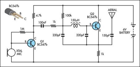
This AM transmitter design is notably simple to construct due to its use of a non-tapped inductor featuring a single winding. The inductor can be conveniently sourced as a standard RF choke, such as the Jaycar Cat LF-1536. To...
A passive light-emitting diode output level indication circuit. This circuit utilizes a light-emitting diode (LED) to provide a visual indication of the output level from a given source. The design is characterized by its passive nature, meaning it does not...
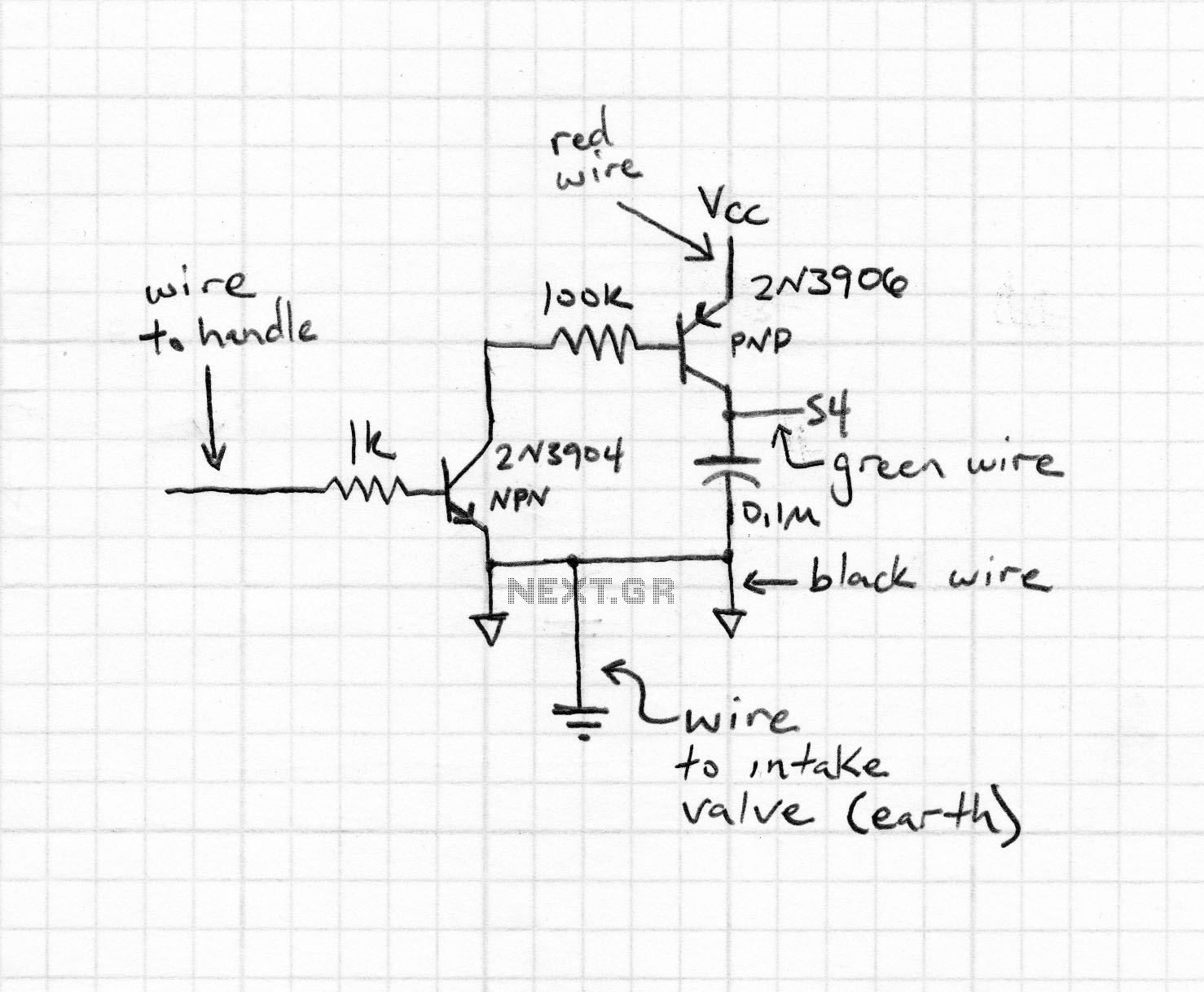
This type of design can produce a very high amperage current for a fraction of a second that can be used to do some useful work if properly harnessed. A point to remember is that Paul Baumann built his...