
Headphone Audio Amplifier with Balance Control

This audio amplifier circuit features a symmetrical design, with both halves mirroring each other to ensure consistent performance across left and right channels. The inclusion of a dual logarithmic potentiometer for input control allows for precise adjustments, accommodating varying input levels. The balance control, implemented as a linear potentiometer, facilitates fine-tuning of signal levels between channels, enhancing the user experience by allowing for personalized audio balance.
The use of 10k resistors at the inputs serves a critical protective function, safeguarding against accidental short circuits to ground, which could otherwise damage the circuit or lead to malfunction. The common emitter amplifier stage is responsible for the initial amplification of the audio signal, characterized by a moderate gain that is sufficient for typical headphone applications. Following this, the emitter follower configuration provides a low-output impedance, enabling the circuit to drive headphones effectively.
The design accommodates 8-ohm headphones, which are common in consumer audio applications, while also supporting higher impedance headphones, making it versatile for various listening scenarios. The 2.2k output resistors play a vital role in maintaining signal integrity by blocking any DC offset that may arise from the coupling capacitors, thereby preventing disruptive sounds when headphones are connected or disconnected.
The self-biasing nature of the circuit simplifies its operation, allowing it to function across a wide range of DC power supply voltages, from 6 to 20 volts. This flexibility makes the circuit suitable for diverse applications, from portable audio devices to more stationary setups. Overall, the design emphasizes reliability, user control, and compatibility with standard audio equipment, making it an effective solution for audio amplification needs.Both halves of the circuit are identical. Both inputs have a dc path to ground via the input 47k control which ought to be a dual log type potentiometer. The balance control is a single 47k linear potentiometer, which at middle modification prevents even attenuation to both left and right input signals.
If the balance control is moved towards the left side, the left input track has less resistance than the right track and the left channel is reduced more than the right side and vice versa. The earlier 10k resitors be definite that neither input can be "shorted" to earth. Amplification of the audio signal is provided by a single stage common emitter amplifier and then via a direct coupled emitter follower.
Overall gain is less than 10 but the final emitter follower stage will directly drive 8 ohm headphones. Higher impedance headphones will work equally well. Note the final 2k2 resistor at each output. This removes the dc potential from the 2200u coupling capacitors and prevents any "thump" being heard when headphones are plugged in.
The circuit is self biasing and designed to work with any power supply from 6 to 20 Volts DC. 🔗 External reference
Related Circuits
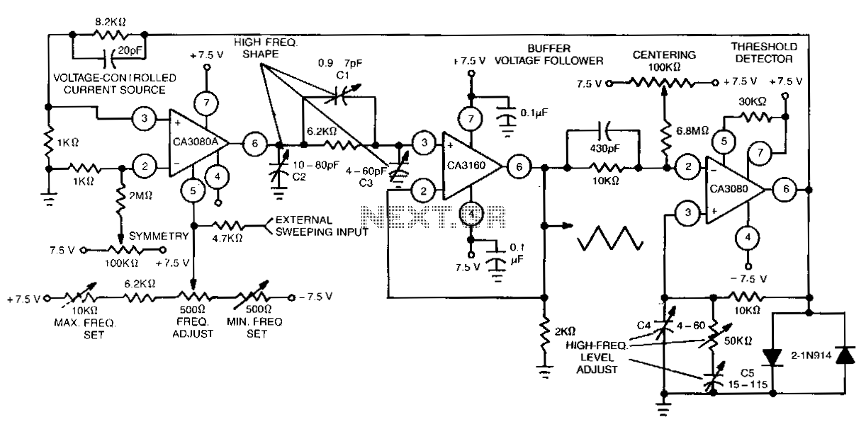
This function generator features an adjustment range exceeding 1,000,000 to 1 and utilizes a CA3160 BiMOS operational amplifier as a voltage follower. It incorporates a CA3080 operational transconductance amplifier (OTA) as a high-speed comparator, alongside another CA3080 configured as...

The gain controller utilizes a 4066 quad bilateral switch to electronically select a feedback resistor for the 741 operational amplifier. One or more switches can be activated simultaneously to achieve a stepped, variable-gain range from less than 1 to...
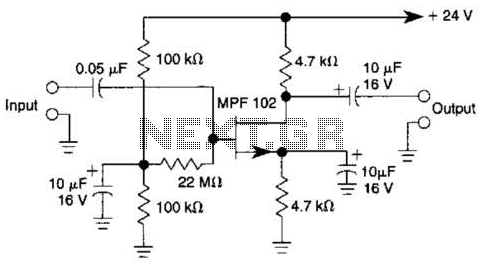
In this amplifier circuit, the gate of the MPF 102 is biased with an external voltage. This circuit achieves tighter control of the operating point and biasing conditions. The amplifier circuit utilizing the MPF 102 field-effect transistor (FET) is designed...
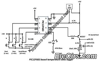
A data logger is a device that records measurements over time. The measurements could be any physical variable like temperature, pressure, voltage, humidity, etc. This project describes how to build a mini logger that records surrounding temperature. A data logger...
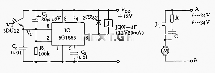
The control circuit consists of an NE555 timer and a phototransistor, along with resistors R1, capacitors C1 and C2, among other components. The photodiodes 3DU12 respond to sunlight by decreasing their resistance, which causes the voltage at the 555...
High-quality amplifier for headphones electronics project. No need for preamplifier. Circuit diagram. The described project involves the design of a high-quality headphone amplifier that operates without the necessity of a preamplifier stage. This simplifies the circuit while still delivering superior...