
Hear Amateurs on your FM Radio!

The proposed circuit design utilizes a direct conversion receiver paired with an FM wireless microphone kit to provide a cost-effective solution for receiving HF signals. The direct conversion receiver operates by mixing the incoming HF signal with a local oscillator frequency, producing an audio frequency output that can be amplified and transmitted.
The essential components of the direct conversion receiver include a radio frequency (RF) amplifier, a mixer, a local oscillator, and a low-pass filter. The RF amplifier boosts the weak incoming HF signals, while the mixer combines these signals with the output from the local oscillator. The local oscillator is typically set to a frequency that is offset from the desired HF signal, allowing for effective downconversion to audio frequencies. The low-pass filter is used to eliminate unwanted high-frequency components from the output signal.
The FM wireless microphone kit serves as the transmission module. It consists of a microphone preamplifier and an FM modulator that converts the audio signal into an FM signal suitable for transmission. The output of the direct conversion receiver is fed into the microphone input of the FM kit, enabling the audio to be broadcast wirelessly.
This setup allows users to receive and listen to HF signals on various devices, such as portable radios and stereo systems, within a certain range of the transmitter. The simplicity of the design makes it particularly suitable for beginners interested in exploring the world of amateur radio without significant investment in multiple HF receivers.
In summary, this circuit effectively combines a straightforward direct conversion receiver with an FM transmission system, facilitating wireless audio monitoring of amateur radio activity across a property.If you`re the sort who`d like to have an HF receiver in every room, but can`t afford it, this idea is for you. It will also appeal to the beginner wishing to build the simplest possible direct conversion receiver.
Using a readily-available FM wireless microphone kit, it is possible to broadcast the audio output of a homebrew direct conversion receiver around your property and beyond. This means that you can monitor amateur activity on your walkman, car radio or stereo system either at home or next door.
🔗 External reference
Related Circuits
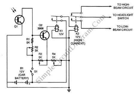
Automatic headlight dimmer circuit diagram for a car's headlight. This circuit ensures maximum brightness for optimal visibility while automatically switching when necessary. The automatic headlight dimmer circuit is designed to enhance driving safety by adjusting the brightness of the vehicle's...
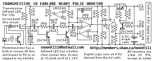
Senses heart pulse by means of an infrared earlobe clip. Reverse engineered circuit diagram of heart pulse sensor circuit board out of a treadmill. Notice that the output is level shifted for use by CMOS logic running on 4.5V...
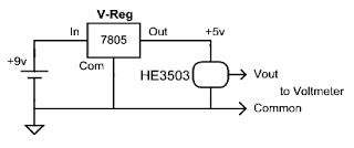
Have you ever wanted to determine the strength of a magnet, observe how the magnetic field strength changes with distance or temperature, or evaluate the effectiveness of a shield placed in front of the magnet? Voltmeters are relatively inexpensive...
Logic-1 and logic-0 represent the states of digital signals, where logic-1 corresponds to a high voltage close to Vcc, and logic-0 corresponds to a voltage near neutral or ground. Logic-0 cannot be transformed into logic-1, while logic-1 can revert...

Creating a variable space in a small room can be enjoyable; however, designing an actuator to move a wall or room partition poses challenges. This can be achieved using an analog audio line delay. To implement a system that allows...
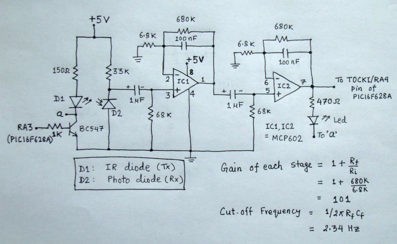
The reflected infrared (IR) signal detected by the photodiode is sent to a signal conditioning circuit, which filters out unwanted signals and amplifies the desired output. The circuit begins with a photodiode that captures the reflected IR signals. The photodiode...