
Automatic Headlight Dimmer Safe Yourself and Others

The automatic headlight dimmer circuit is designed to enhance driving safety by adjusting the brightness of the vehicle's headlights based on surrounding light conditions. The primary components of this circuit typically include a light-dependent resistor (LDR), a transistor, a relay, and a diode.
The LDR serves as a sensor that detects ambient light levels. In daylight, the resistance of the LDR is low, which keeps the transistor in a non-conductive state, preventing the relay from activating. As the surrounding light diminishes, the resistance of the LDR increases, allowing the transistor to conduct, which subsequently energizes the relay. This action engages the headlight circuit, switching the headlights to a higher brightness setting.
A diode is included in the circuit to protect against back EMF generated by the relay coil when it is de-energized. This prevents potential damage to the transistor and other components in the circuit. The design may also incorporate adjustable resistors to fine-tune the sensitivity of the LDR, allowing for customization based on user preferences or specific driving conditions.
The schematic typically illustrates the connections between these components, indicating the power supply, ground paths, and signal flow. Proper layout and component selection are crucial to ensure reliable operation and responsiveness of the automatic dimming feature, ultimately contributing to a safer driving experience.Automatic headlight dimmer circuit diagram for your car`s headlight, keep you safe with maximum bright for farthest visibility, but will automatically switch . 🔗 External reference
Related Circuits
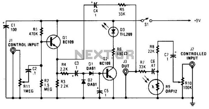
In this circuit, audio input to the control channel is amplified and rectified by diodes D1 and D2. This direct current level activates LED D3 through transistor Q2. The illumination from LED D3 causes R9, a light-dependent resistor, to...
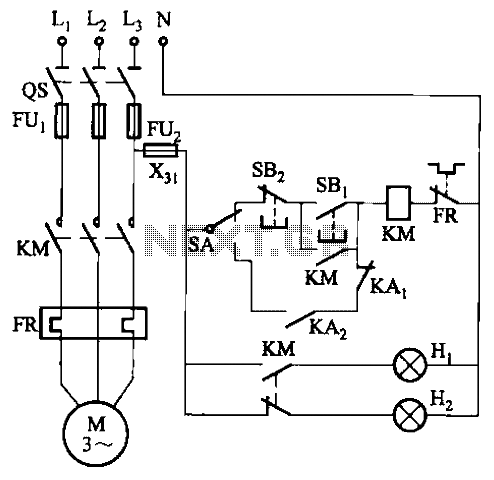
In certain locations near the reservoir or well, when the water level is constrained by the water towers, there is a need for simultaneous monitoring of the water towers and reservoirs as part of an automatic water control system....
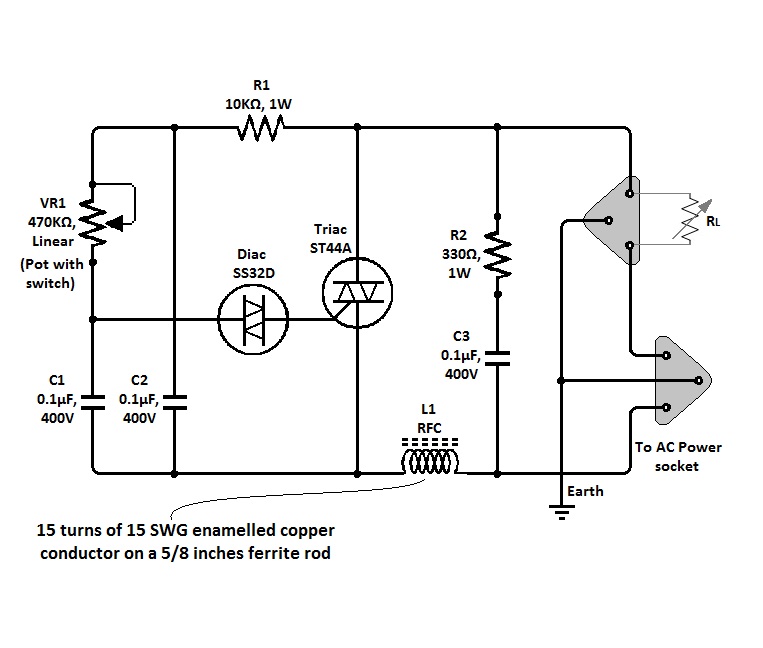
The circuit of a simple triac light dimmer can be used to dim incandescent lamps directly from AC mains. It is easy to construct and requires very few components. A potentiometer is utilized to control the load power or...
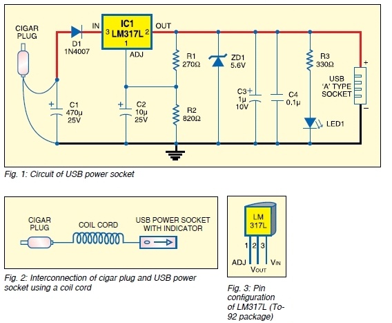
The safe 12V car adapter described here can be used to limit the current from a +12 volt car battery, available from the in-dash cigar lighter power port, to below 2.6A. The 12V car adapter is designed to ensure that...
Typical segment display LEDs consume around 25 mA for each segment and should be limited to this current with resistors. For a six-digit display to be current limited, at least 42 series resistors are needed. The brightness of the...
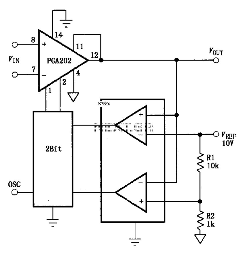
The automatic range switching circuit consists of PGA202, comparators, and counters, as illustrated in the figure. The comparator at the output compares VOUT with VREF. When VOUT exceeds 10V, the comparator generates a low signal, causing the up/down counter...