
Heart Monitor (ECG Sensor Signal Amplifier/Conditioner)
")
The heart pulse monitoring circuit typically consists of several key components that work together to accurately detect and amplify the electrical signals generated by the heart. The primary components include:
1. **Electrodes**: These are placed on the patient's skin to detect the electrical activity of the heart. Common configurations include a pair of electrodes placed on the chest or limbs.
2. **Buffer Amplifier**: The initial stage of the circuit is usually a buffer amplifier. This component is essential for isolating the electrodes from the subsequent amplification stages, preventing loading effects that could distort the signal. Operational amplifiers (op-amps) configured as voltage followers are commonly used for this purpose.
3. **Gain Stage**: Following the buffer, a gain stage amplifies the weak electrical signals detected by the electrodes. This stage typically involves one or more op-amps configured to provide a significant gain, often adjustable based on the specific requirements of the monitoring application.
4. **Filtering**: To ensure that only the relevant heart signal frequencies are processed, the circuit may include a filtering stage. This stage can utilize passive filters (resistors, capacitors) or active filters (using op-amps) to eliminate noise and interference from other electrical signals.
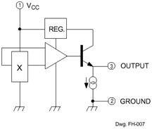
5. **Output Stage**: The final stage of the circuit is designed to present the amplified and filtered signal in a usable format. This could involve further amplification for driving a display, an analog-to-digital converter for digital output, or a wireless transmitter for remote monitoring.
6. **Power Supply**: The circuit requires a stable power supply to ensure consistent operation. Battery power is often preferred for portability, while regulated power supplies may be used in stationary applications.
This heart pulse monitoring circuit is crucial for various medical applications, including real-time patient monitoring in hospitals and remote health tracking for individuals. Proper design considerations, such as component selection and circuit layout, are vital to ensure accurate and reliable performance.Using the circuit depicted in the schematic diagram below we can monitor the heart pulses of patient. This circuit buffer and amplify the heart pulses, and the.. 🔗 External reference
Related Circuits
Strain-gauge sensors convert strain into an electrical signal for applications in pressure sensors, weight measurements, force and torque measurements, and materials analysis. A strain gauge functions as a resistor, with its resistance value changing in response to strain. Strain-gauge sensors...
.png)
The one-touch turn signal (OTTS) module enhances the functionality of the turn signal lever by adding a mode where a single touch makes the indicators blink for a certain number of times. This behavior is also known as lane...
The Hall Effect sensor generates a voltage that is proportional to the strength of the magnetic field it detects. This sensor consists of a silicon layer with two electrodes on either side. In the absence of a magnetic field,...
To obtain an accurate pressure value, it is essential to eliminate offset errors. Numerous basic circuit designs are employed to remove these offset errors. Offset errors in pressure measurement systems can lead to inaccuracies in the readings, which may affect...
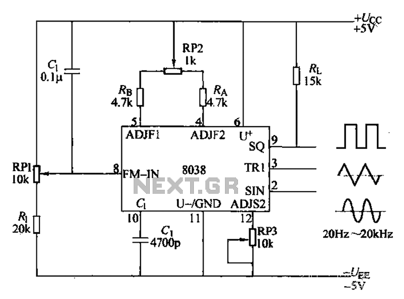
The audio function generator integrated circuit ICL8038 is capable of producing square waves, triangle waves, and sine waves. The electrical resistance and potentiometer RP1 are utilized to determine the 8-pin DC potential Ua, which is typically set to 2Ucr/3....
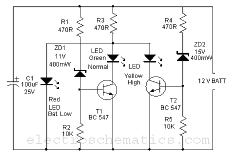
This is a simple battery monitor circuit designed for a quick assessment of a 12-volt lead-acid battery. Continuous monitoring of battery charge is essential to extend its lifespan. The battery monitor circuit typically consists of a voltage divider, an operational...