
Heat Sensor Circuit using LM741

The Simple Heat Sensor Circuit is designed to detect temperature changes and can activate a relay when a specific temperature threshold is exceeded. The circuit primarily employs the LM741 operational amplifier, which serves as a comparator to process the input signals from the temperature sensor.
The components used in the circuit include:
- **Re1 (Relay 12V)**: This relay acts as a switch that is controlled by the output of the LM741. When the temperature exceeds the set point, the relay will close, allowing current to flow through connected devices, such as a fan or alarm system.
- **R1 (47K ohm resistor)**: This resistor is part of the input stage of the circuit and helps set the gain of the operational amplifier.
- **R2 (150K and 390K ohm resistors)**: These resistors are used to form a voltage divider or to set reference voltages for the operational amplifier, ensuring that it operates within the desired voltage range.
- **R3 (1.8K ohm resistor)**: This resistor may be used in conjunction with the other resistors to stabilize the circuit and control the feedback loop of the operational amplifier.
- **R4 and R5 (2.2K ohm resistors)**: These resistors are likely used for biasing purposes or as part of the feedback network for the operational amplifier.
- **P1 (50K Trimmer Potentiometer)**: This adjustable resistor allows for fine-tuning of the circuit's sensitivity, enabling the user to set the temperature threshold at which the relay will activate.
- **IC1 (LM741)**: The LM741 operational amplifier is the core of the circuit, functioning as a comparator. It compares the voltage from the temperature sensor (Th1) with a reference voltage set by the resistors. When the input voltage exceeds the reference voltage, the output of the LM741 changes state, triggering the relay.
- **Q1 (2N2222 or 2N3904 Transistor)**: This transistor acts as a switch that can amplify the current driving the relay, ensuring that it operates effectively without being overloaded.
- **D1 (1N4148 Diode)**: This diode is used for flyback protection across the relay coil, preventing voltage spikes that could damage other components when the relay is de-energized.
- **Th1 (10K Thermistor)**: This temperature sensor changes its resistance with temperature variations. It is the primary component that detects changes in heat, providing the input signal to the operational amplifier.
The design of the circuit allows for a straightforward assembly and tuning process, making it suitable for various applications such as temperature monitoring systems, HVAC controls, or safety alarms. Proper attention should be given to the power supply requirements and the layout of the components to ensure optimal performance and reliability of the heat sensor circuit.The following page outlines detail information on how to step by step design a Simple Heat Sensor Circuit. This circuit design utilized LM741 as the operational amplifier. Circuit Parts/Components List: Re1 = 12V relay R1 = 47K R2 = 150 390K R3 = 1K8, R4, R5 = 2K2 P1 = 50K Trimmer Pot IC1 = LM741, LM741CN-ND, LM741CN, NE741, μA741, etc. Q1 = 2N2222 2N2222 2N3904-ND D1 = 1N4148 Th1 = 10K 🔗 External reference
Related Circuits
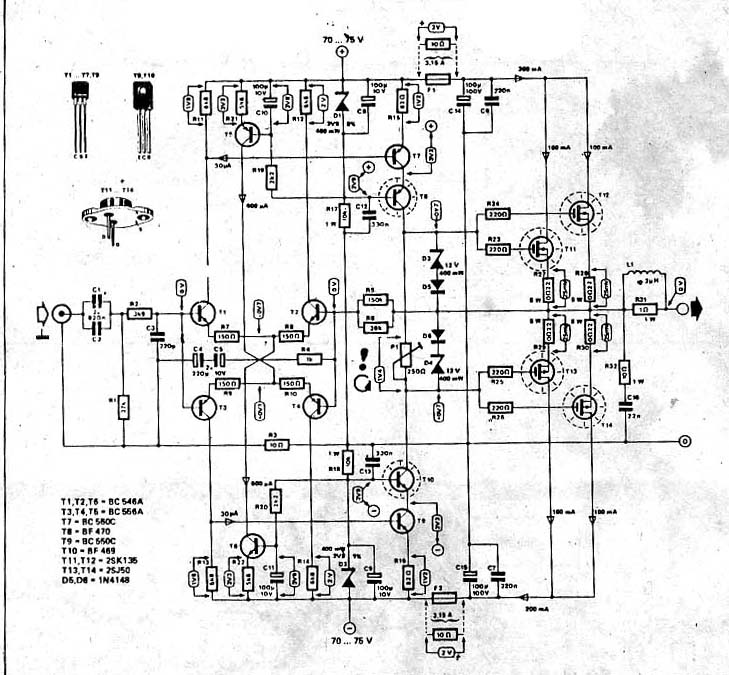
The power amplifier circuit utilizing MOSFET technology has gained significant popularity due to its aggressive sound characteristics when compared to traditional transistors and integrated circuits. It offers both low-frequency and high-frequency responses and is known for its durability. Generally,...
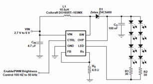
The schematic diagrams for the TPS61042 current LED driver illustrate its capability to power eight LEDs with an efficiency of 81% at 3.6V and 18.6mA. The TPS61042 is commonly utilized in applications such as white LED supply for backlight...
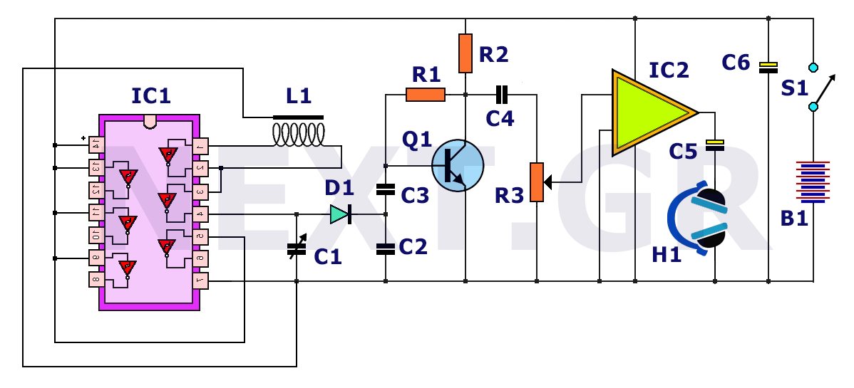
The principle behind a metal detector is quite simple. This is demonstrated by the following circuit, which shows that a metal detector can be constructed quickly with a few readily available components. This metal detector circuit can detect a...
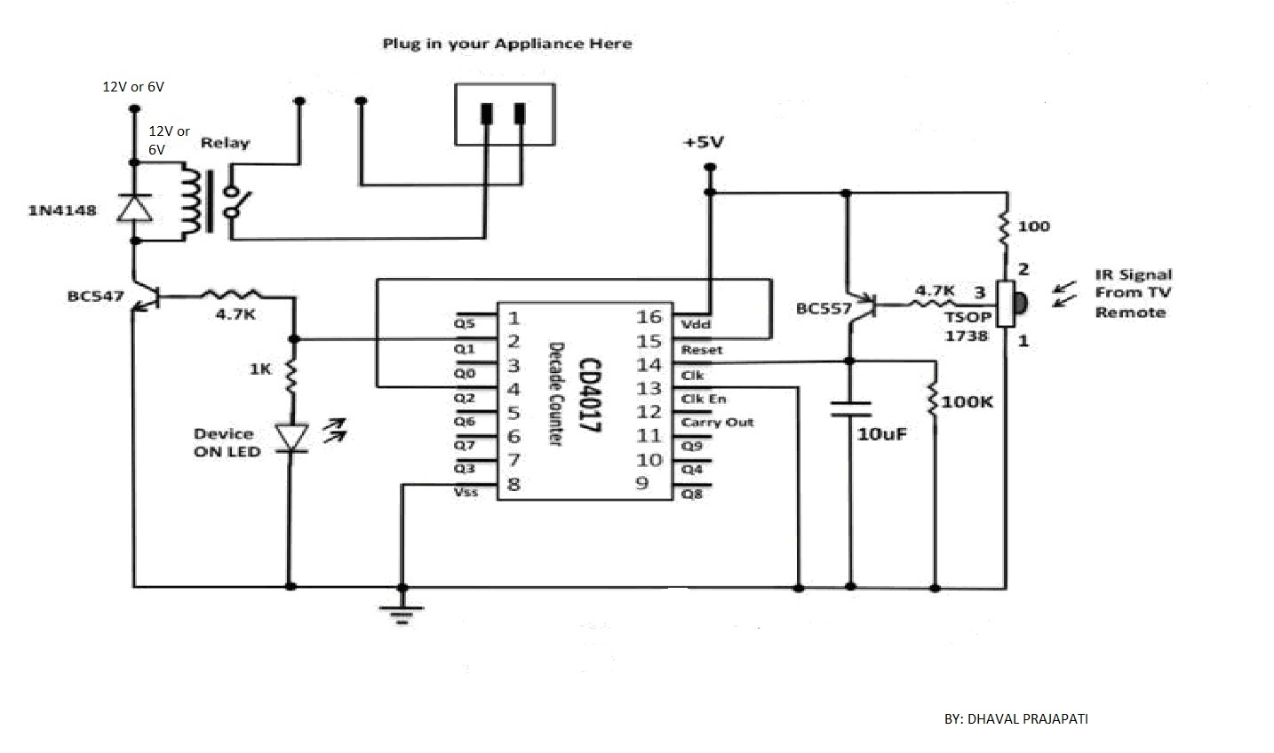
The circuit utilizes a 4-bit encoder to generate data, which is then modulated using an RF modulator for transmission. On the receiving end, the signal is demodulated, and a decoder retrieves the 4-bit data. The pin configuration for the...
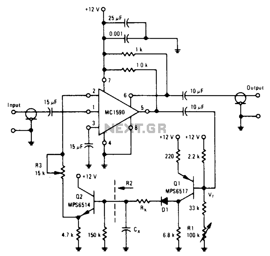
An amplifier designed to achieve a voltage gain of approximately 20, utilizing the MPS6517 PNP transistor in the emitter follower configuration. The RI controller allows for adjustment of the transistor's quiescent point. The output signal is activated only when...
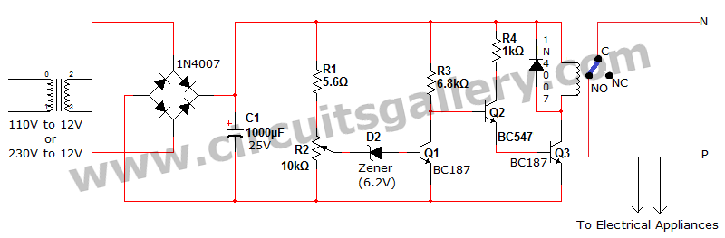
Voltage fluctuation is a significant concern in residential settings. For various reasons, the supply voltage may exceed 110V or 230V. This excessive voltage can potentially damage household electrical devices. An effective solution for electrical protection is the implementation of...