
Simple Over Voltage Protection Circuit: High Voltage Cut Off

The over-voltage protection circuit utilizes a Zener diode to regulate voltage levels, ensuring that the output voltage remains within safe limits for connected devices. The Zener diode operates in reverse bias, allowing it to maintain a constant voltage across its terminals when the input voltage exceeds the specified threshold. This characteristic is crucial for preventing damage to sensitive electronic components.
The circuit typically includes a relay, which acts as a switch to control the power supply to the connected devices. The relay is energized when the input voltage is within acceptable limits, allowing current to flow to the load. However, if the input voltage rises above the predetermined level, the Zener diode conducts, triggering the relay driver (Q3) to turn off. This action deactivates the relay, cutting off the power supply and protecting the devices from potential damage due to excessive voltage.
In addition to the Zener diode and relay, the circuit may include additional components such as resistors and capacitors to stabilize operation and filter out noise. The design can be tailored to accommodate various voltage levels and load requirements, making it versatile for different applications. Overall, this over-voltage protection circuit is a practical solution for enhancing the safety and longevity of electrical appliances in residential environments.Voltage fluctuation is a serious issue in every home. Due to some reasons our supply voltage may rise above 110V or 230V. Flow of this high electricity may lead to the damage of our home electrical devices. Have you thought how electrical protection is possible via a simple over voltage protection circuit Here CG comes with an interesting over vo ltage protection device to protect your electrical appliances from getting damaged. Zener diode voltage regulator is the main part of this high voltage cut off circuit. You can implement this over voltage protection relay circuit in your home as a high voltage regulator. Q3 is our relay driver, turning OFF of Q3 shuts down the relay too. When relay is OFF, there will be no supply of electricity to the device. Hence they are protected from over voltage. 🔗 External reference
Related Circuits
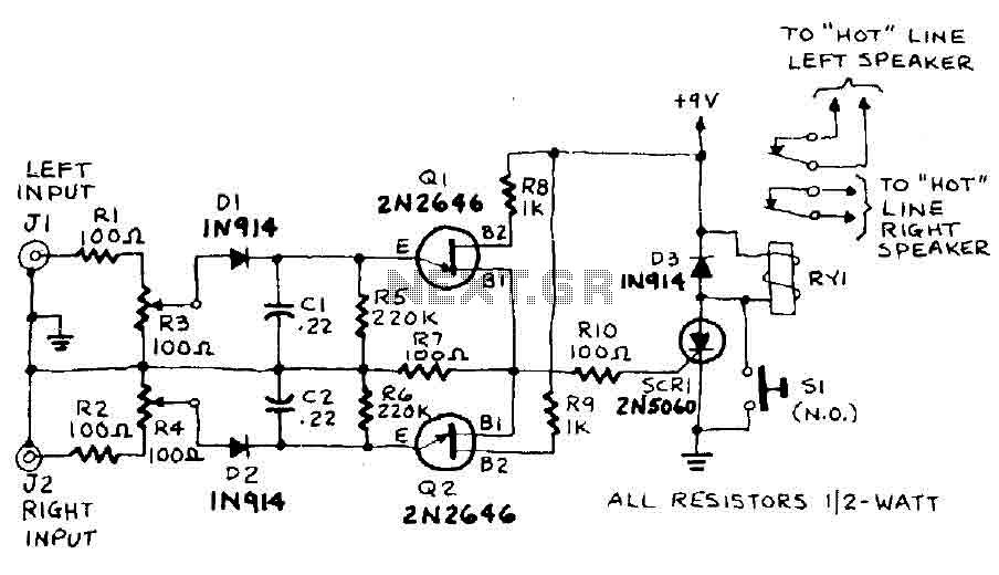
The circuit input is derived from the terminal loudspeaker or amplifier output jacks. If the right channel signal is sufficiently strong to charge capacitor C1 to a potential that exceeds the breakdown voltage of the emitter of transistor Q1,...

One way to provide effective negative-voltage regulation is by using a low-dropout positive-voltage regulator operating from a well-isolated secondary winding of a switch-mode circuit transformer. This technique is applicable to any positive-voltage regulator, although the highest efficiency is achieved...
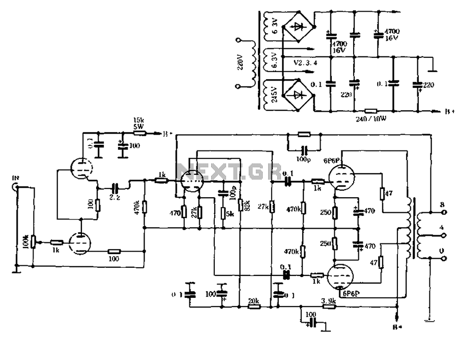
The self-generated bias amplifier tube is designed for each tube individually to alleviate the challenges faced by amateur conditions in paired amplifiers. It includes a separate DC filament power supply, which minimizes the risk of induced cross-linking and enhances...
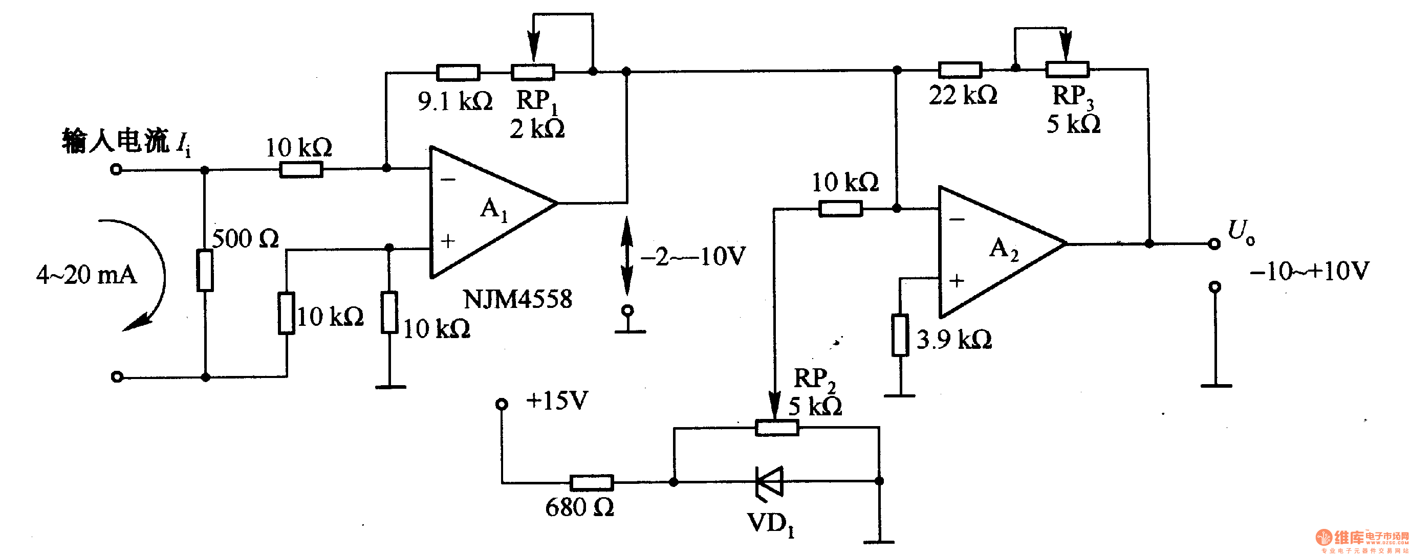
Figure 1-42 (a) is a voltage/current conversion circuit that converts a 0-10V input voltage into a 4-20mA output current. Adjusting resistor RP2 can set the input voltage (Ui) to 0V, resulting in an output current (I) of 20mA; similarly,...
Due to the huge interest in this project, I have just recently finished the NEW schematics. The older schematics were scanned and pretty poor quality. These new ones should make it considerably easier to recognize the parts used for...
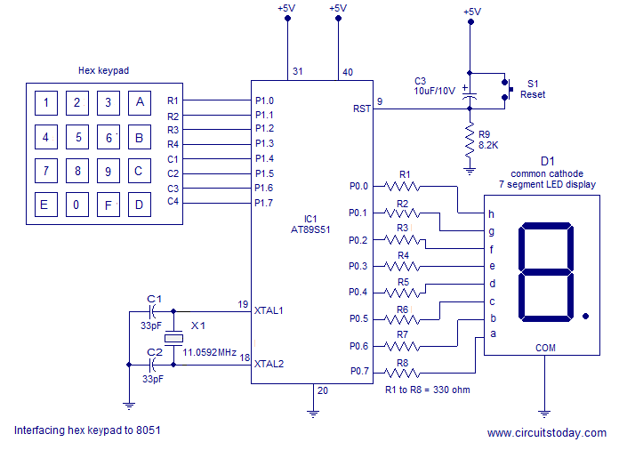
Interfacing a hex keypad to an 8051 microcontroller. The AT89S51 is utilized in this setup. A circuit diagram and assembly language program are included. A testing video is also provided. The interfacing of a hex keypad with the AT89S51 microcontroller...