
Heating System Thermostat Circuit

The described circuit functions as a temperature control system, integrating both indoor and outdoor temperature sensors to maintain optimal heating conditions. The primary components of this circuit typically include temperature sensors, a microcontroller or comparator, relays or solid-state switches, and a power supply.
The indoor temperature sensor monitors the current temperature within the living space, while the outdoor temperature sensor assesses external conditions. The microcontroller processes the data from both sensors to determine whether to activate or deactivate the heating system. This decision is based on pre-defined temperature thresholds that can be adjusted according to user preferences or seasonal requirements.
For actuation, the circuit employs relays or solid-state switches, which are responsible for controlling the power supplied to the heating elements, such as electric heaters or a boiler. The reliability of the design is enhanced through the use of robust components and the implementation of fail-safes to prevent overheating or system failure.
Additionally, the circuit may incorporate features such as a user interface for temperature setting adjustments, LED indicators to signal system status, and communication interfaces for integration with smart home systems. Overall, this temperature control circuit is designed to ensure efficient operation and comfort in heating applications, adapting to varying environmental conditions.Controlled by indoor and outdoor temperature, Simple, high reliability design This circuit is intended to control a heating system or central heating plan.. 🔗 External reference
Related Circuits
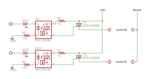
Many projects involve 120VAC and require relatively slow switching. While mechanical relays are commonly used in such situations, they are often avoided due to the presence of moving parts. Solid-state relays (SSRs) have been utilized previously, but their high...
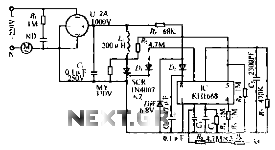
The synchronous vibration circuit operates with a control logic that includes three primary components. An internal oscillator is initiated by a synchronization pulse, transitioning to a low state immediately after the pulse. Upon power activation, the internal circuitry undergoes...
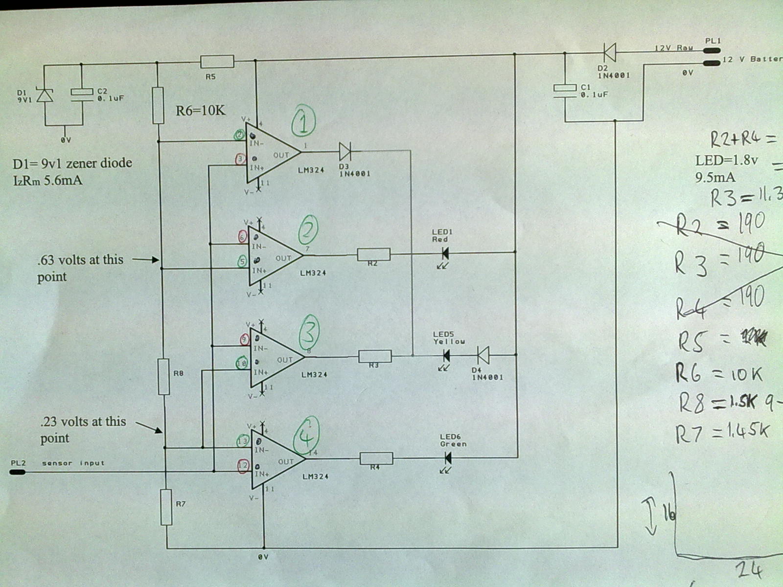
A 12V power supply is connected to the positive terminal, allowing current to flow through a protection diode and a capacitor that smooths the voltage. A zener resistor (R5) limits the current to the zener diode, which regulates the...
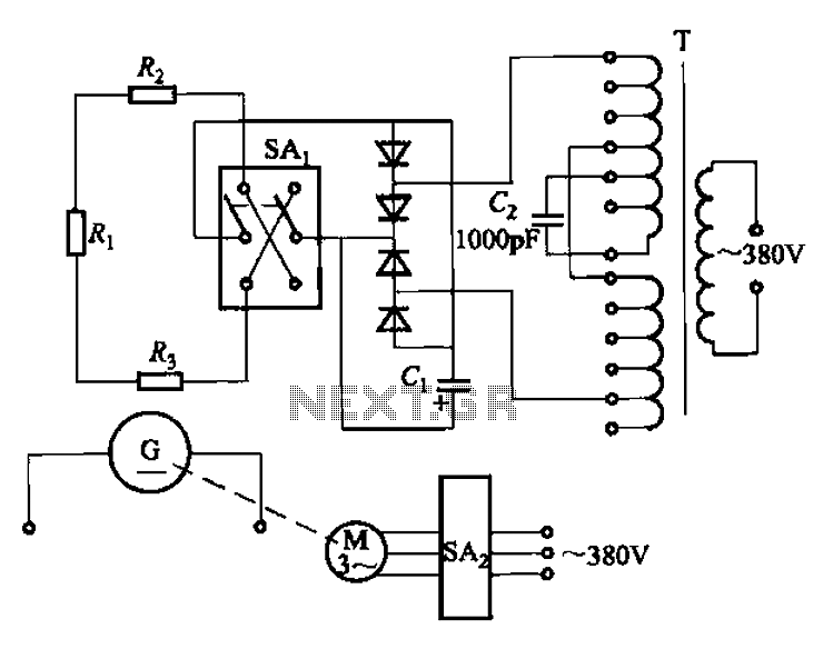
The AR-300 DC arc welding machine circuit includes the AX, AX1, AX3, and AR series. The structure of these machines is fundamentally similar, consisting of a three-integral unit converter, a phase asynchronous motor, and a DC arc welding generator...
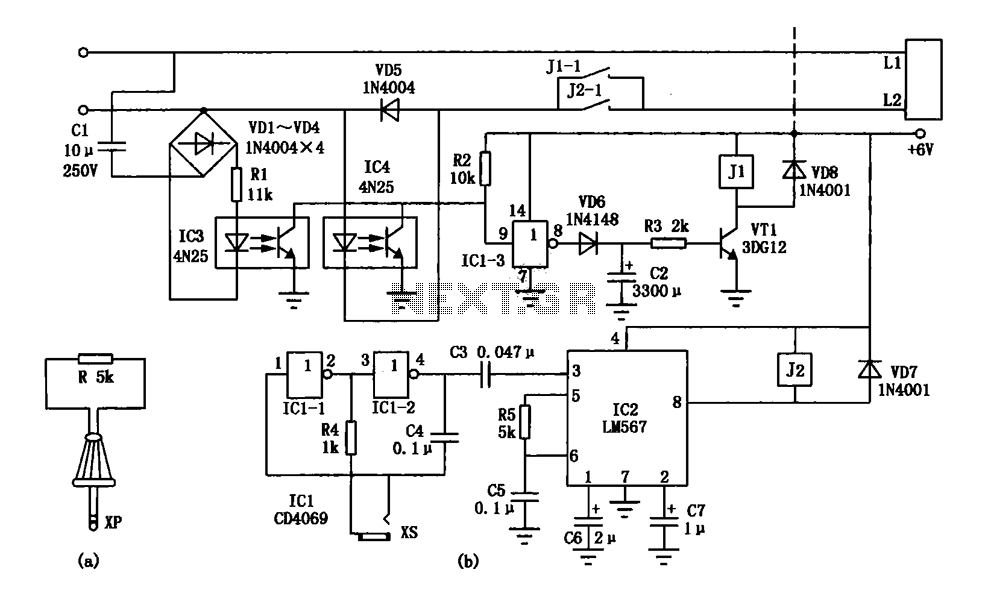
An electronic lock utilizing a telephone key, which is connected through a resistor plug, is integrated after the oscillator circuit's startup phase. The accuracy of the oscillation frequency determines whether the phone can be used for outgoing calls, while...
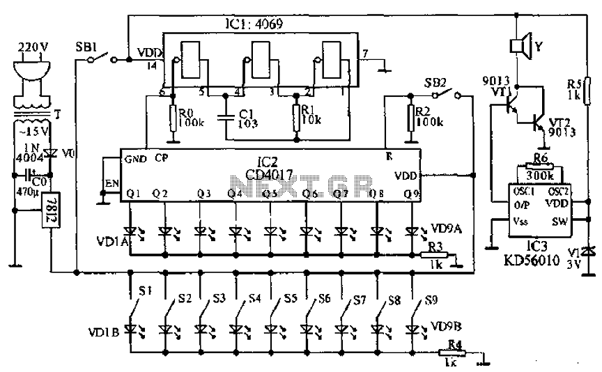
This document presents a principle circuit for electronic games. The main circuit operates in conjunction with the host through the reset button SB2, while the indicators VD1A-VD9A remain off. Prizes, for example, five, are determined by the number of...