
Triac circuit

The circuit design utilizing Triacs for controlling 120VAC applications involves a few key components. A Triac is a semiconductor device that can control AC power. It is triggered into conduction by a gate signal, allowing current to flow through it. This makes it ideal for applications requiring on/off control of AC loads.
The circuit typically includes a Triac, a diac or an optoisolator for triggering, and a snubber circuit to protect against voltage spikes. The optoisolator provides electrical isolation between the control circuit and the high-voltage AC circuit, enhancing safety while allowing for remote control.
In a basic configuration, the Triac is connected in series with the load, which could be a lamp or any other AC device. The gate of the Triac is driven by a control signal, which can be generated by a microcontroller or a simple switch. When the gate receives a trigger pulse, the Triac turns on and allows current to flow through the load. The snubber circuit, typically comprising a resistor and capacitor in series, is placed across the Triac to absorb voltage transients and protect the device from damage.
This design not only reduces the overall cost compared to SSRs but also simplifies the physical layout, allowing for a more compact package. The ability to independently control two power plugs further enhances the versatility of the circuit, making it suitable for various applications where AC control is needed. The entire assembly can be housed in a small enclosure, ensuring that it remains user-friendly and efficient.A lot of my projects involve 120VAC, switching relatively slowly. Most people use mechanical relays in that situation, but I don`t like them; I try to avoid moving parts whenever possible. Up to this point, I`ve always used solid state relays. They work really well, but they`re expensive. What this means is that I`ve needed to move my same 2 SSRs from project to project, which is kind of a pain. Well no more! Enter the humble Triac. They`re tiny, cheap, and in my slow switching applications the circuitry isn`t too complicated. That being said, it`s still the most complicated circuit I`ve ever attempted. And there you have it. A neat little package with two independently controlled power plugs. The best part is the cost. The whole thing cost less then $10! With SSRs it would have been ~$80, and I don`t know if they even would have fit in the box. 🔗 External reference
Related Circuits
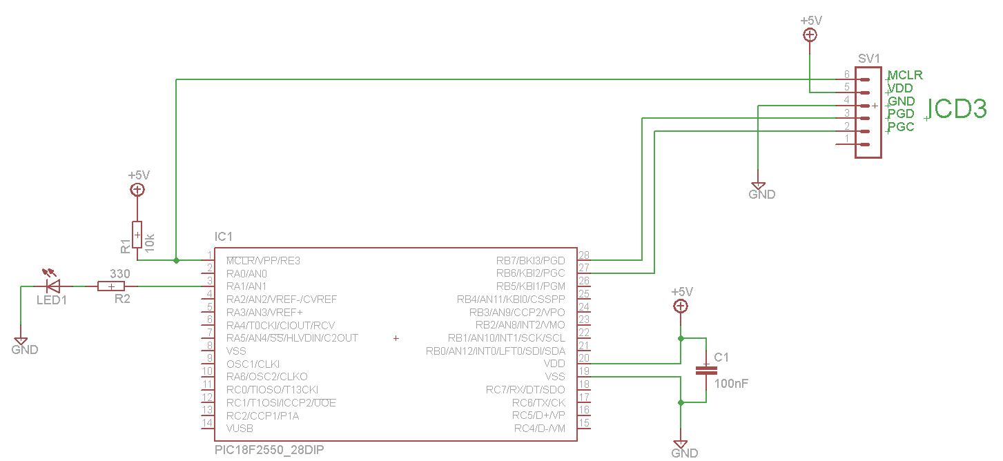
The LED blinks as expected, then pauses for an indefinite duration, flashes again a different number of times, and turns off again, displaying no discernible cyclic behavior. It activates without any external input, indicating that there is likely no...
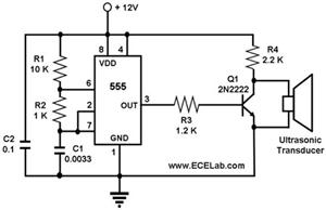
The ultrasonic cleaning machine functions as a humidifier and operates on a simple circuit primarily consisting of an ultrasonic oscillator. It generates ultrasonic frequency signals, typically within the range of 20-40 kHz, using a transistor. These signals are transmitted...
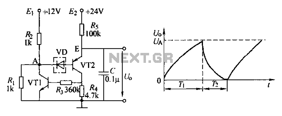
The application circuit depicted is a complementary sawtooth generator. In the schematic, VT1 is the transistor with a base current limiting resistor, which prevents excessive base current flow through the crystal tube. The resistor R4 acts as a bleeder...

This light dimmer is designed to adjust the brightness of 12V light bulbs utilizing the widely recognized 555 timer, which is configured as an astable multivibrator. The pulses generated by the timer control the power delivered to the light...

The basic connection circuit for the ISO103 signal and power supply is illustrated. Each power supply terminal must include a bypass filter. If the isolated power supply output current exceeds 15mA, it is advisable to utilize an external filter...

The HA7210 oscillator, in conjunction with the IOL7642 quad CMOS operational amplifier, forms a sleep-mode control circuit. This circuit can enter sleep mode when a logic high is applied to the Reset input or through an RC timer that...