
HETERODYNE FREQUENCY METER

The circuit is designed to operate within a frequency range of 1 to 40 MHz, utilizing a combination of oscillation and mixing techniques to detect and analyze RF signals. The oscillator (Q1) generates a stable frequency output, which serves as a reference for the untuned mixer (X1). The mixer facilitates the combination of the unknown RF signal with the oscillator's output, producing an intermediate frequency that can be processed by the audio frequency beat-note amplifier (Q2).
The calibration of capacitor C4 is critical for accurate frequency measurement. It allows for direct readings of the oscillator frequency, ensuring that the system can effectively zero-beat with the incoming RF signal. The zero-beating technique is essential for identifying the frequency of the unknown signal, as it relies on achieving a condition where the beat frequency is minimized, resulting in an audible tone through the connected magnetic headphones.
The use of inductors L1 and L2 is significant in the circuit's design. L1, with its 65 turns, provides the necessary inductive reactance to facilitate the mixing process, while L2, with its 10 closely wound turns, enhances the circuit's performance by improving the coupling between the oscillator and the mixer. The tapping of L1 at 20 turns allows for flexibility in tuning and adjusting the circuit to achieve optimal performance across the specified frequency ranges.
Overall, this circuit exemplifies a practical application of RF technology in signal detection and analysis, making it a valuable tool for engineers and technicians working in the field of electronics. Its straightforward design and calibration process make it accessible for various applications, including communication systems and signal processing tasks.Circuit consists of 1-2 MHz oscillator Q1, untuned mixer X1, and AF beat-note amplifier Q2. C4 is calibrated to read directly in frequency from 1 to 2 MHz, using accurate unmodulated RF signalgenerator. After calibration, unknown RF signal input frequency is fed into meter for zero-beating with harmonics of calibrated oscillator.
Magnetic headphone s plugged into J1 make beat note audible. On second harmonic, dial of C4 covers 2-4 MHz; on twentieth harmonic, coverage is 20-. 40 MHz. L1 is 65 tums No. 28 enamel on 1-inch form, tapped 20 tums from ground. L2 is 10 tums No. 28 enamel closewound around center of L1. -R. P. Turner, "FET Circuits, " Howard W. Sams, Indianapolis, IN, 1977, 2nd Ed. , p 144-146. 🔗 External reference
Related Circuits
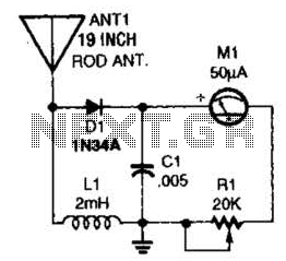
This basic field-strength meter offers an affordable solution for monitoring an amateur radio or CB transmitter, as well as an antenna system, to ensure maximum output. The field-strength meter is designed to measure the strength of radio frequency (RF) signals...
This is a very simple circuit utilizing a 555 timer IC to generate a square wave of frequency that can be adjusted by a potentiometer. With values given, the frequency can be adjusted from a few Hz to several...
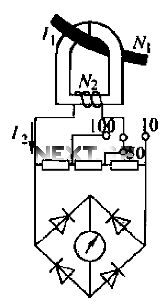
An ammeter measures current in a circuit, requiring the circuit to be interrupted in series for measurement. A clamp meter, however, allows for direct measurement of current without breaking the circuit. The clamp meter's structural principle relies on a...

Phase noise is a critical performance parameter of frequency synthesizers for wireless applications. RF system designers of phase-modulated cellular systems, such as PHS, GSM, and IS-54, require low noise local oscillator (L.O.) or frequency synthesizer blocks. This document describes...
This is a circuit schematic diagram for VU meters. The circuit is controlled by the IC TL072 and follows a measurement circuit as per the National general application. The input circuit around IC1 is designed for adaptation and amplification...
The circuit includes a peak detector that immediately drives the readout to any new higher signal level and slowly lowers it after the signal drops to zero. The readout is a moving dot or expanding bar display. The circuit...