
Hewlett-Packard HP-200C audio oscillator

The HP-200C oscillator is a significant advancement in audio-frequency generation technology, designed to overcome common issues associated with traditional oscillators. Its Wien bridge configuration allows for precise frequency tuning, while the light bulb feedback mechanism enhances stability and performance across a wide frequency range. The oscillator operates efficiently within the audio spectrum and extends into the VLF radio range, making it suitable for various applications in electronics and communications.
The construction of the HP-200C involves critical components such as vacuum tubes, which serve as amplifiers and oscillators, providing the necessary gain and frequency generation. The use of a 20 µF electrolytic capacitor in the output stage is noteworthy, as it plays a crucial role in shaping the output signal while potentially introducing a DC bias, which must be managed when interfacing with other audio equipment.
The historical context of the HP-200 series highlights its significance in the evolution of electronic test equipment. The challenges faced by early audio oscillators, such as stability and portability, were addressed through innovative design solutions implemented by Hewlett and Packard. The legacy of the HP-200C continues to influence modern oscillator designs, emphasizing the importance of reliability and accuracy in electronic measurements.After repairing a couple of Hewlett Packard vacuum tube voltmeters, I read up on some of the company history. I was able to locate a HP-200C oscillator. This HP-200C is very close in design to the company`s initial product. It is a Wien bridge resistance-tuned oscillator with the famous light-bulb stabilized negative feedback circuit designed by W
iliam Hewlett while doing graduate work at Stanford. (Patent #2268872. Application filed in 1939 and granted in 1942) The original HP-200 was built and sold out of Hewlett`s garage with fellow Stanford grad David Packard, marking the founding of Hewlett-Packard. I did not have a schematic for the 200C but the schematic for the 200I was close enough with nearly identical vacuum tubes (6F6, 6V6, and 6SJ7 for electrically identical 6J7) in the oscillator and amplifier circuits.
Output for the 200C is specified as 100 milliwatts, 10 volts into a 1000 ohm load. Although this is labeled an audio oscillator, and it does indeed cover the full audio spectrum, its upper range is well beyond audio, in the VLF radio range at 200 KHz. The HP-200C was in rather rough condition and had not been powered for many years. I used contact cleaner on the range switch and the volume control. The volume control had not tracked properly, but opening it and applying contact cleaner directly solved the problem.
The power switch also showed no continuity. Contact cleaner was applied through the bat handle with the switch facing upwards. That cured the switch problem. The power cord was replaced with a new grounded cable. This was followed by a thorough cleaning of the set and checking for safety and a proper level of resistance in the B+ line. The rectifier was pulled out and a variac used to power the set slowly for just the filaments and checking for proper AC voltages at the rectifier socket.
This was followed by a slow power-up with the rectifier in and reforming the electrolytics properly. A check with my oscilloscope showed the unit working on all its ranges. Using a frequency counter, the cap was adjusted for best dial accuracy. Apparently some of the range resistors had ben replaced earlier in its life. Dial accuracy from one range to another confirmed that the resistors were still in good order. I noticed a low level DC bias on the output of the oscillator but learned from the 200I manual that that was normal. A 20 MFD electrolytic is used as the output capacitor. I am assuming that some leakage in the cap is the cause of the DC bias. The 200I manual warns against using the output on a high-quality audio transformer because of the DC component.
The next generation HP-200CD uses special transformers for output. The 200C proved quite stable on the scope, performing as intended. I could see the stabilizing action of the negative feedback light bulb element when switching ranges. An early HP catalog details the circuit principle and the advantages and uses for the device. "THERE is a sound research story behind this revolutionary -hp- Resistance-tuned Audio Oscillator. Although audio-frequency oscillators have always been standard equipment throughout the communications and electronics fields, there were many "bugs" in types commonly available.
These disadvantages included low stability, especially in the lower frequency ranges; need for constant resetting to insure accuracy; low portability, because of the essential weight and bulk of the instrument. So -hp- engineers set out to design and perfect an audio-frequency oscillator which would combine the high stability and very wide range of the coil-condenser type with the flexibility of operation of the best frequency type.
The result is the basically new Resistance-tuned Audio-frequency Oscillator, based on a new fundamental circuit and resulting in new speed and accuracy for electronic tests and measurements. " (HP catalog 1945) 🔗 External reference
Related Circuits
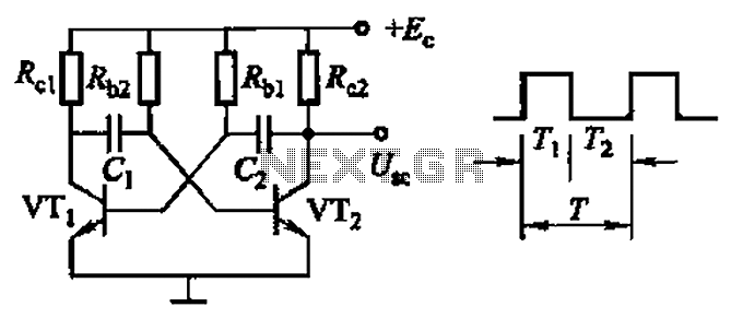
Common non-sinusoidal oscillator circuit, waveform and frequency formula - square wave oscillator - self-excited multivibrator The common non-sinusoidal oscillator circuit, specifically the square wave oscillator, is a fundamental electronic circuit utilized to generate square wave signals. It operates based on...
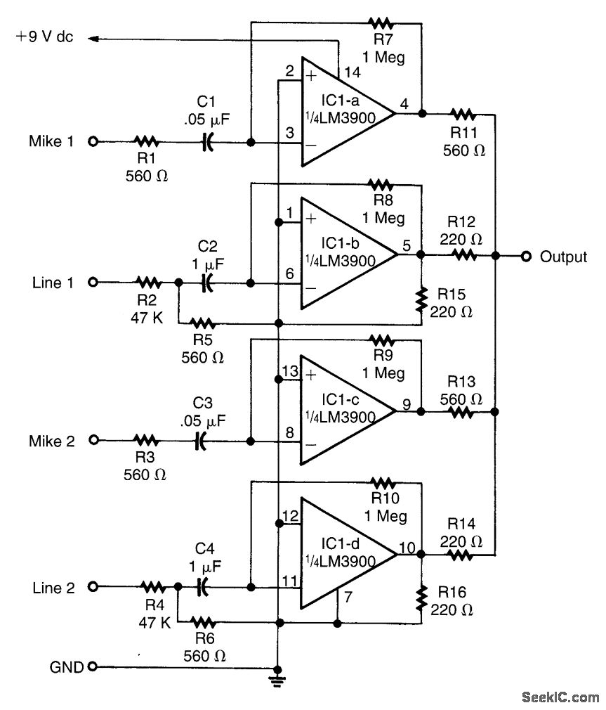
This circuit is designed around an LM3900 quad operational amplifier, which combines two line inputs and two microphone inputs, summing them at the output terminal. Resistors R7 through R10 can be adjusted to vary the gain, approximately +23 dB. The...
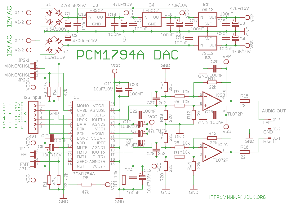
A transformer with two separate 12V secondary windings is required for the power supply. If the transformer does not have a third separate winding, the supply input of the S/PDIF decoder must be connected in parallel to the positive...
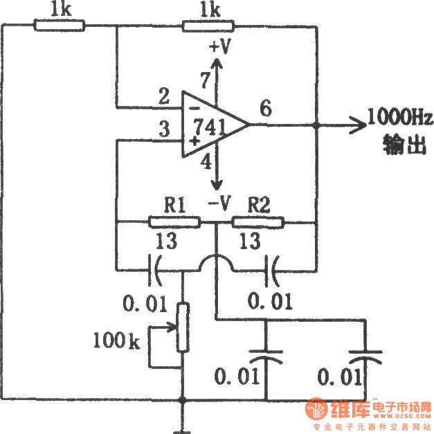
The circuit illustrated in the diagram is a 1 kHz sine wave oscillator circuit. Based on a double-T circuit configuration, it utilizes a standard 741 operational amplifier to generate a 1000 Hz sine wave output. The circuit begins oscillation...
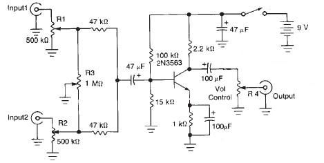
This audio mixer circuit diagram electronic project is designed using a few common electronic components. The audio mixer circuit project has two input channels. The input signal can be independently controlled using the R1 and R2 variable resistors. The...
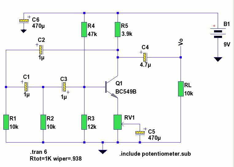
The circuit is a standard RC phase shift oscillator that utilizes a single bipolar transistor as the active component. When power is supplied, regenerative feedback is applied through capacitor C2 from the collector to the base of the transistor....