
1kHz sine wave oscillator(741)
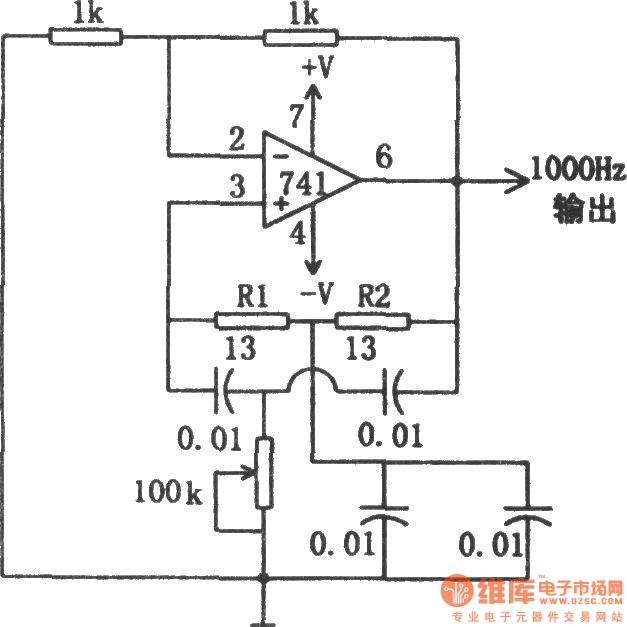
The described circuit employs a double-T oscillator topology, which is renowned for its simplicity and effectiveness in producing sine wave outputs. The heart of the circuit is the 741 operational amplifier, a widely used component in analog applications due to its versatility and availability. In this configuration, the operational amplifier is set up to provide necessary gain and feedback, which are crucial for sustaining oscillations.
The oscillation starts when the 100 kΩ potentiometer is adjusted, allowing fine-tuning of the circuit's threshold for initiating oscillation. The resistors R1 and R2 play a pivotal role in determining the frequency of oscillation. Their values, typically chosen for a 1 kHz output, must be carefully calculated to ensure that the circuit resonates at the desired frequency. The relationship between these resistors and the feedback network defines the oscillation frequency, following the formula for a double-T oscillator.
Additionally, the circuit may include capacitors in the feedback loop to stabilize the oscillation and filter any unwanted high-frequency noise. Proper selection of these capacitors is essential to maintain the integrity of the sine wave output. The output of the circuit can be connected to various loads, such as audio applications or signal processing circuits, where a stable sine wave is required.
Overall, this 1 kHz sine wave oscillator circuit exemplifies the fundamental principles of analog signal generation and can serve as a foundational design for more complex applications in electronic engineering.The circuit shown in the chart is 1kHz sine wave oscillator circuit. Basing on the double-T circuit, the circuit using 741ordinary operational amplifier to produce 1000Hz sine wave output. Adjusting 100k? potentiometer will make circuit start oscillation, the oscillation frequency is determined by R1 and R2, and under normal circumstances, the value of two..
🔗 External reference
Related Circuits
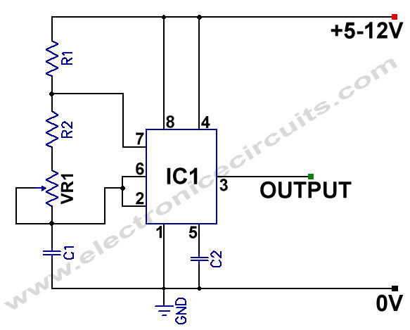
555 Variable Frequency Square Wave Generator. This simple 555 Variable Frequency Square Wave Generator produces a variable frequency output. The 555 Variable Frequency Square Wave Generator is a versatile circuit that utilizes the 555 timer IC to generate square wave...
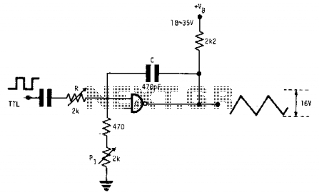
This fixed-frequency triangular waveform generator, driven by a TTL square wave, produces triangular waveforms with a peak-to-peak voltage of typically 16 V at frequencies reaching several MHz. The design utilizes a single AND open collector gate or an open...
This sine wave generator is adjustable between 15 Hz and 150 kHz. The circuit is essentially a Wien-bridge oscillator, featuring multiple capacitor selections. The sine wave generator operates on the principle of the Wien-bridge oscillator, which is known for producing...
Using only a single transistor and a few passive components, a fairly sensitive peak detector circuit can be built. This peak detector circuit is suitable for various applications. The peak detector circuit utilizes a single transistor, typically configured in a...
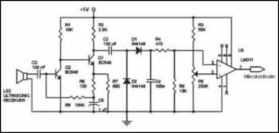
Ultrasonic receivers detect an ultrasonic signal emitted by an ultrasonic transmitter at a specific frequency. The received signal is filtered using a band-pass filter circuit that allows only the predetermined frequency range to pass. The output signal is then...
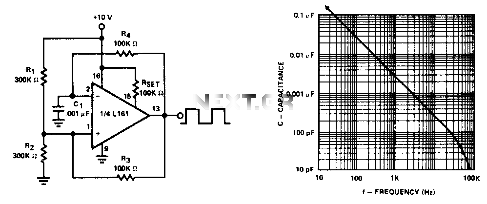
This generator operates at frequencies exceeding 100 kHz. The lower frequency limit is determined by capacitor Cl. Additionally, the frequency remains constant for supply voltages down to +5 V. The generator described is a versatile electronic oscillator capable of producing...