
HF GENERATOR using a 68HCx11


The GHF1 generator is designed to provide a versatile frequency generation solution, operating effectively across both high-frequency (HF) and low-frequency (LF) bands, spanning from 30 Hz to 30 MHz. The device's architecture incorporates the MAX038 integrated circuit, which is pivotal in generating a stable sinusoidal output. The output signal's amplitude is maintained at 2 Vpp, ensuring a consistent performance across the operating frequency ranges.
The selection of frequency ranges is facilitated through a range switch (Sw1), which allows the user to choose between six different capacitors (C11 or C15) connected to pin 5 of the MAX038. The generated frequency is modulated by an adjustable current (Iin) that is derived from a voltage divider formed by the multi-turn potentiometer (P1) and resistor (R3). This design ensures fine control over the output frequency, allowing for precise tuning.
Modulation capabilities are extensive, with the generator supporting both amplitude modulation (AM) and frequency modulation (FM). The modulation signals are produced by the XR2206, which is adept at generating the necessary waveforms for AM and FM applications. The modulation depth can be adjusted through potentiometer P3, providing flexibility in signal characteristics. The XR2206 also synchronizes with external equipment via a negative pulse output on pin 11, which is useful for oscilloscope triggering during frequency sweeps.
The amplifier stage utilizes the MAX477, which is capable of operating up to 300 MHz. It is configured in a non-inverting manner, and the gain is adjustable based on the resistive components in the feedback loop. The output stage is designed to deliver a robust signal capable of driving a 50-ohm load, with output levels reaching approximately +10 dBm.
For applications requiring signal attenuation, the GHF1 includes a four-cell attenuator, allowing for adjustments of 10 dB and 20 dB. This feature is particularly beneficial for testing and measurement setups where signal levels need to be controlled.
The sweep function of the GHF1 is implemented using a sawtooth waveform generated by IC5A, which is then processed to create a rectangular output for triggering purposes. The timing and position of the trigger can be finely adjusted using the AJ5 potentiometer, ensuring synchronization with the desired measurement intervals.
Overall, the GHF1 generator represents a significant advancement over traditional heterodyne generators, offering improved performance, flexibility, and ease of use for a wide range of electronic applications.The GHF1 is a small generator covering the HF and LF band from 30 Hz to 30 MHz in 6 ranges. The sinusoidal signal obtained can be amplitude modulated (AM) or frequency (FM). The GHF1 also has a sweep function. An LCD display 2 x 16 characters allows the frequency, mode and selected for each, the modulation rate, the value of the trip sweep. GHF1 claims to replace the generators of the past, (often called at that time "heterodyne") with significantly better performance.
Unlike these old generators which were type LC, switched coils and lines for variable capacitor for adjusting the frequency, GHF1 is of the type RC, which allows excellent MAX038 from MAXIM. At the heart of the scheme the MAXO38. This circuit delivers on its pin 19 a perfectly constant amplitude signal of 2 Vpp. The sinusoidal shape is selected by A1 (pin 4) to +5 V and A0 (Pin 3) to 0. The frequency is determined by the capacitor connected to pin 5. Either C11 or C15 Caj selected from 6 by the switch Sw1 ranges. In each range, the frequency is determined by the current injected into the stud 10 (Iin). This current is equal to U P1 / R3. It is therefore determined by the multi-P1 and voltage follower iC3b. The coverage ratio is around 10. Vernier frequency is added. This is obtained by varying the voltage applied to the pin 8 (FADJI). This voltage is determined by a second multi-P2 and the voltage applied to the + input of iC3b. This entry serves us for FM and sweep. In the first case, we inject a sinusoidal voltage from 400 to 1000 Hz, amplitude 100 mVpp about. In the second case, a sawtooth downward approximately 1.75 VDC. The exact levels of these tensions will be resolved in finalizing by AJ2 (VOBU) or AJ3 (FM) The modulation signals are generated by XR2206 , which is perfect for this mission. They are obtained on the pin 2. The level is adjustable from 0 to max, for P3a. A switching Sw2 skips the sine to sawtooth. The frequency of the sine wave is adjustable from 400 to 1000 Hz, by P4. This ramp is 8 to 50 Hz approximately, P5. The output level of these signals is calibrated by AJ1 The XR2206 gives its pin 11 on a top negative for synchronizing the oscilloscope associated mode sweep.
On the right side of the diagram we distinguish: The amplifier output . (Top) is given by a MAX477 MAXIM for a bandwidth up to 300 MHz. The resistor R20 provides an output at 50 W . The input level is adjustable by P6. The amp is mounted in non inverter and its gain is determined by R19 and the resistance of the JFET Type J300. We have G = (R19 + R J300 ) / R J300. The strength of the J300 is a function of its gate voltage. The quiescent point is adjusted by AJ4. BF tension after the XR2206 function allows to obtain an AM modulation depth from 0 to 50% depending on the position of P3.
The calibration will be done by developing AJ1. The maximum output voltage of HF is about 5 VDC, in 6 of the MAX477, which provides half of this voltage on a load of 50 W or so about +10 dBm, which is far to be negligible. The GHF1 is complemented by an attenuator to 4 cells: 1 and 3 to 10 dB 20 dB Compare the trigger .
(bottom) In steady sweep, the frequency must be set to the center frequency of the tour. The sawtooth, centered on 0 V is applied IC5A whose output provides a rectangular slot, negative during the first half of the ramp and positive for the other. The amp IC5b reverse this signal which, in these conditions has its down side in the middle ramp. It is this side that provides the triggering of the measure. See below The adjustable AJ5 can place this measure exactly in the middle of the ramp. 🔗 External reference
Related Circuits
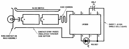
The schematic presented below illustrates the Flashlight Finder circuit diagram utilizing the LM3909, a monolithic oscillator specifically designed for flashing Light Emitting Diodes (LEDs). The Flashlight Finder circuit employs the LM3909 integrated circuit, which is capable of generating a series...
The circuit presented is a 20W audio amplifier utilizing the LM1875 integrated circuit (IC). The LM1875 is a high-quality, low-distortion audio amplifier IC rated for 20 watts, available in a TO-220 package. This IC includes several built-in features such...
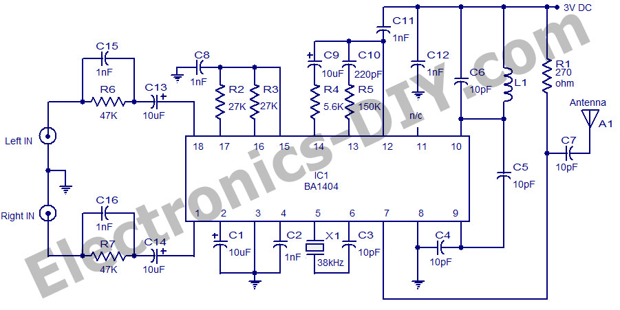
A high-quality stereo FM transmitter circuit is presented here. The circuit utilizes the IC BA1404 from ROHM Semiconductors. The BA1404 is a monolithic FM stereo modulator that incorporates a built-in stereo modulator, FM modulator, and RF amplifier circuitry. The...
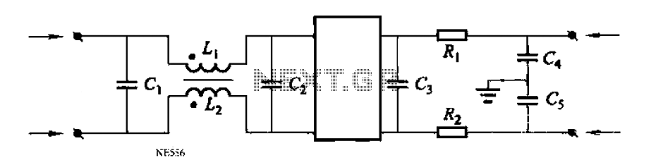
Automated instrumentation wiring using interference filters for the inverter is not as effective for harmonic processing. When operational, it will radiate a strong field strength due to high amplitude electromagnetic waves. If the meter is installed in the automation...
This signal generator is designed for the realignment of radio receivers. It is an economical and straightforward unit, adequate for its intended application. However, the output is not a pure sine wave, which may limit its suitability for more...
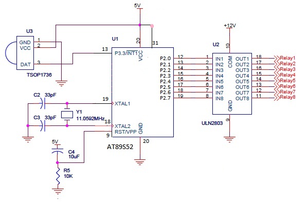
The infrared (IR) circuit is designed to control multiple devices using a TV remote. Unlike standard circuits that can typically switch only one device, this circuit allows for the operation of different devices with the same remote by utilizing...