
HF reciever with MC3362

The circuit design described involves a high-frequency (HF) receiver system utilizing an MC3362 integrated circuit from Motorola, which is well-suited for FM demodulation applications. The initial stage of the circuit is an HF amplifier (T1) that boosts the incoming signal captured by the antenna. The gain of the amplifier can be adjusted by varying its supply voltage, allowing for a gain range of 20 dB, which significantly enhances the signal strength.
The first mixer within the circuit uses a quartz oscillator (QZ1) set to a frequency derived from the received signal, specifically tuned to generate a local oscillation at 10.7 MHz. This frequency is filtered through an XF106 filter to ensure that only the desired frequency components are passed to the second mixer. The second mixer utilizes another quartz oscillator operating at 10.245 kHz to down-convert the signal to an intermediate frequency of 455 kHz, which is then filtered using a CFW455 filter.
The 455 kHz signal undergoes further amplification through a six-stage amplifier, which not only amplifies the signal but also provides a direct current (DC) output proportional to the received signal strength indicator (RSSI). This DC output is then processed by additional transistors (T2 and T3), which form an automatic gain control (AGC) loop to maintain optimal operating conditions for the HF amplifier (T1).
The design emphasizes compactness, with the RX17 and RX18 models featuring dimensions that cater to subminiature applications. The RX17 model can be assembled in two configurations, with the use of HC45 quartz and an aluminum case, ensuring a lightweight and robust design. The RX18 offers a more cost-effective solution with a mono-printed board that retains the same functionality but in a thinner profile.
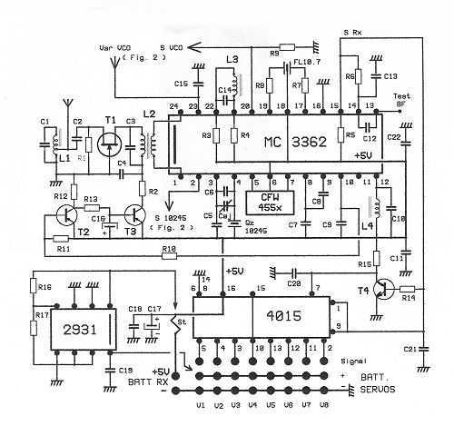
Overall, the described circuit provides a reliable and efficient solution for receiving high-frequency signals, with careful attention to gain control and compact design, making it suitable for a variety of installations where space is a constraint.The diagram of detail of Fig.2 gives additional precise details: The signal HF collected by the antenna is amplified by T1, framed reel S of agreement L1 and L2. To vary the profit of T1, it is enough to vary its supply voltage. Here it passes from 4v to 0V, the varying profit of +10 dB with - 10 dB, is 20 dB on the whole. It is far from bebeing negligible! All the remainder of the assembly is integrated in a MC3362 from MOTOROLA. To notice quartz QZ1 ensuring the local oscillation of first mixer. Its frequency is of Freq/reçue- 10700 in kHz, so as to come out of the 10.7 MHz, filtered by a XF106 of KVG.
Applied to second mixer with its quartz of 10245 kHz, we obtain from the 455 kHz, filtered by a traditional CFW455. The 455 kHz is treated in-house by an amplifier on 6 floors which supplies a discriminator FM granted by L4.
This amplifier delivers at the same time a D.C. current proportional to the intensity of the received field. (RSSI). This current is amplified by T2 and T3 and allows the control of the profit of T1. You initially finds in fig. 1 the simplified diagram of the assembly. You see the HF amplifier T1, two mixers delivering one the 10.7 MHz, the other the 455 kHz then the saturated amplifier with the 455 kHz. Finally the FM demodulator and the output comparator which provides a rectangular signal to the logic of decoding.
Let us note also the AGC chain with transistors T2 and T3 for gain control of T1 T1. The RX17-2 wants to be subminiature. For that purpose, we use quartz out of case HC45, without support. According to the manner of assembling it, the RX17 measurement either 27x32x23 mm or 32x38x16 mm. See photographs. In both cases, volume is of 19.5 Cm3 and the weight of 22 G, out of case aluminum of 6/10, without particular precaution. For these two versions, it is possible to come out the connectors, either with the square of the circuits, or in the prolongation.
See photographs. This second provision makes it possible to have a receiver of 16mm overall thickness, which facilitates its installation in the narrowest cells. For this provision, an additional plate, envisaged in the layout of the circuit, is to be welded onto the line of the barbs " signal ".
The junction being done only by the weldings, without plug wire. The RX18 is a mono-printed board version of the RX17. It thus has same surface 31x51 mm, but with a thickness half. Using ordinary quartz, the 10245 kHz welded and QZ1 onto support, it is a little less expensive than the RX17. It measures overall 32x52x18 mm and weights 30 g. It is thus a receiver which is appropriate perfectly for the majority of the installations. The absence of connection by wire between receiver and decoder accroit reliability. As for the RX17, the connectors assemble themselves either to the square, or parallel to U principal circuit.
🔗 External reference
Related Circuits
This scanner uses a DDS circuit to scan through the frequency band. Since a DDS is used to set the desired frequency, this receiver can jump from one frequency to another within microseconds, making it very fast. The receiver...
This receptor is born of our annoyance against the irritating problem of Quartz: With the RX21, completed research of cut crystal for your personal rating, you have with him, access to ALL band frequencies, in steps of 5 kHz!...
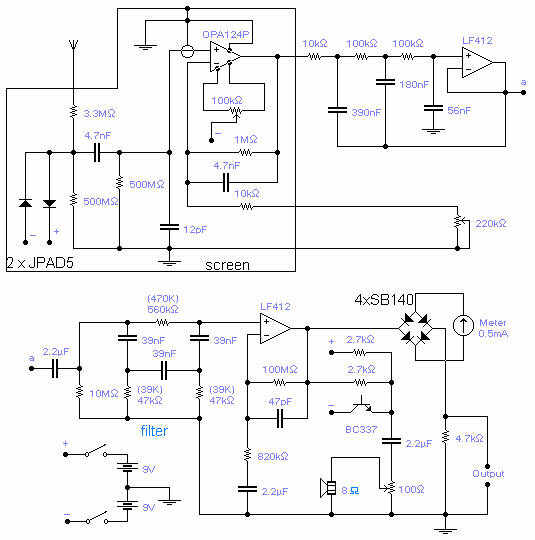
The frequency covered is from 0.1Hz to 10Hz and useful signals are received up to 16Hz. The first Op-Amp, properly shielded, must be installed close to the antenna (1-3m long) and connected to the rest of the circuit with...
This is a measurement I did on a FM receiver (MC3372). I have plotted the output DC-bias as a function of the IF (Intermediate Frequency) frequency. At 455kHz you can see that I have 5.5V DC bias. When I...

The 7MHz CW transceiver is constructed using the MC3362P integrated circuit, originally intended for a 10MHz band transceiver. Due to concerns regarding unexpected neighboring spurious signals, the frequency was altered to 7MHz, leading to the completion of the transceiver....
The performance of this sensitive ultrasonic receiver is impressive. It allows users to listen to various sources of ultrasonic sounds, including insects, bats, engines, and more. The circuit employs a piezo tweeter as an ultrasonic microphone, along with amplifier...