
0.1Hz to 10Hz RF reciever

The described circuit operates within a frequency range of 0.1Hz to 10Hz, with the ability to receive useful signals up to 16Hz. The initial component in the design is an operational amplifier (Op-Amp), specifically the OPA124, which should be installed in close proximity to the antenna (within 1-3 meters) to minimize noise pickup. A 5-core shielded cable connects the Op-Amp to the remaining circuit, ensuring signal integrity by reducing electromagnetic interference.
The circuit features a trimmer potentiometer of 100kΩ, which is crucial for fine-tuning the DC output of the OPA124. This adjustment must ensure that the DC setting remains stable while varying the 220kΩ sensitivity potentiometer. To mitigate mains-induced noise, a low pass filter is implemented, followed by a notch filter specifically designed to target noise at 60Hz. It is recommended that 1% tolerance components be utilized for the three resistors and three capacitors within the notch filter to maintain precision in filtering.
Additionally, a voltage-controlled oscillator (VCO) is integrated into the design, producing an audible frequency that tracks the input signal. This feature enhances portability, although it has been noted that movement in the vicinity can obscure the received signal. The output of the circuit is routed first to a meter for immediate readout and subsequently made available for connection to a data logger, which is an essential component for data acquisition.
The circuit's sensitivity is notably high, capable of detecting signals from nearby electronic devices, such as television sets. The design includes input protection diodes, which are of a low leakage type to prevent signal degradation; standard diodes should not be used as replacements. These diodes may be omitted if the antenna is strategically placed away from strong electric fields. Furthermore, Schottky diodes are employed in conjunction with the meter, providing a bias that filters out insignificant noise signals from reaching the data logger.
Pin connections for the OPA124 are as follows: pins 1 and 5 are used for DC setting, pins 2 and 3 serve as the inverting and non-inverting inputs, pin 6 is the output, and pin 8 is connected to the substrate. For the LF412, the pin configuration is: pins 2 and 3 are inverting and non-inverting inputs, pin 1 is the output, and pins 6 and 5 are additional inverting and non-inverting inputs, with pin 7 being another output. This configuration allows for versatile signal processing within the circuit.The frequency covered is from 0.1Hz to 10Hz and useful signals are received up to 16Hz. The first Op-Amp, properly shielded, must be installed close to the antenna (1-3m long) and connected to the rest of the circuit with a 5-core shielded cable. Adjust the 100k trimmer so that the DC setting at the output of the OPA124 does not change when turning the 220k sensitivity pot.
A low pass filter followed by a notch filter take care of the mains induced noise. The values in brackets are good for a 60Hz mains. 1% components should be used for the 3 resistors and 3 capacitors of the notch filter. A voltage controlled oscillator gives an audible frequency that follows the input signal and it is very handy if the unit is made portable although I found that just walking around is enough to bury the signal being received. The output signal goes first to a meter and then is available for the connection to a data logger, which is an almost essential part of the receiver.
Sensitivity is quite adequate: any TV set switching on in the area will be detected. There are also a host of other mysterious signals of unknown origin. The input protection diodes are special low leakage type and should not be replaced by standard diodes. These diodes can be dispensed with if the antenna is installed with care and away from strong electric fields.
The diodes connected to the meter are Schottky diodes and will provide a bias against very small signals (mostly noise) which will not go through to the data logger. Pin connection for OPA124: 1 and 5: DC set, 2 and 3: inverting and non-inverting, 6: output, 8: substrate.
Pin connection for LF412: 2 and 3: inverting and non-inverting, 1: output, 6 and 5: inverting and non-inverting, 7: output. 🔗 External reference
Related Circuits
This receptor is born of our annoyance against the irritating problem of Quartz: With the RX21, completed research of cut crystal for your personal rating, you have with him, access to ALL band frequencies, in steps of 5 kHz!...

With the P1 we regulate the intensity of sound. With the P2 we regulate the frequency of reception. Optionally: If you want to check the frequency with your PC it will be supposed you make the following energies: You...

This circuit is designed to generate audio musical notes that can be heard from a distance of up to 10 meters. The circuit consists of two main components: an infrared (IR) music transmitter and an IR music receiver. The...
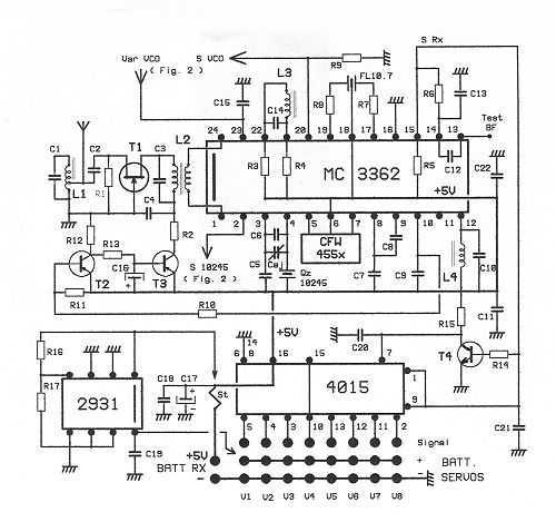
The radio IC is in the middle of the board. Above the IC you will find a ceramic filter (10.7MHz) for the FM part. This filter is blue. At the top you will find the yellow AM IF filter....
This is a measurement I did on a FM receiver (MC3372). I have plotted the output DC-bias as a function of the IF (Intermediate Frequency) frequency. At 455kHz you can see that I have 5.5V DC bias. When I...
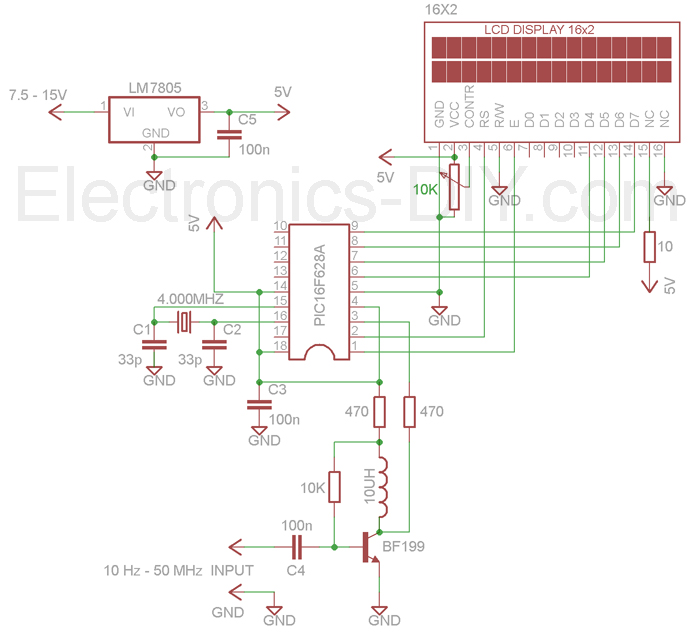
The 60MHz Frequency Meter/Counter measures frequencies from 10Hz to 60MHz with a resolution of 10Hz. This device serves as highly effective bench test equipment for testing and measuring the frequency of oscillators, transmitters, radio receivers, function generators, crystals, and...