
Scanner Reciever for 78-80 MHz with PIC16F84

One disadvantage is that many crystals are needed, and one must know which crystal frequency to use. Once built, changing the frequency is not easy. Next-generation scanners employ PLL (Phase Lock Loop) synthesizers, which control a VCO and lock it to the desired frequency. These synthesizers can control a VCO over a wide frequency range with good stability. However, PLLs require some locking time to stabilize at a frequency, determined by a locking filter (RC filter). To achieve a stable system, this locking time must be relatively long, several milliseconds.
The RF signal enters through the antenna and is amplified by a preamplifier before reaching the first mixer, which is connected to a crystal oscillator. In this case, a 45.18125 MHz crystal is used. For instance, to receive an RF signal at 79.6625 MHz, the first mixer mixes the RF with 45.18125 MHz and its double frequency, 90.3625 MHz. The output from this mixer is 90.3625 - 79.6625 = 10.7 MHz. The choice of a 45 MHz crystal and the use of the second overtone (90 MHz) in the mixer is based on the availability of the crystal from an old radio. Alternatively, a third overtone crystal at 68 MHz could be used, yielding the same IF product from the mixer.
At the output of the first mixer is a passband filter, 2-3 MHz wide, allowing frequencies from 9-11 MHz to pass while attenuating others. The resultant signal (10.7 MHz in this example) enters the second mixer, where a DDS circuit produces a sinusoidal signal programmable from 9-11 MHz via the CPU. For this example, the DDS is set to 10.245 MHz. A low-pass filter cleans the signal, rejecting overtones and glitches before it enters the second mixer. The output product from this mixer is 10.7 - 10.245 = 455 kHz, which is passed through a sharp 455 kHz ceramic filter before entering the FM demodulator, extracting the audio signal.
If the DDS were not set to 10.245 MHz, the input to the second mixer could vary based on the DDS frequency limits of 9 MHz and 11 MHz. The input RF frequency can be calculated as follows:
Max receiving frequency = 90.3625 - 9.455 = 80.907 MHz
Min receiving frequency = 90.3625 - 11.455 = 78.907 MHz
Thus, by adjusting the DDS frequency from 9 to 11 MHz, the scanner can receive frequencies ranging from 78.9 to 80.9 MHz. The DDS can be programmed with a resolution of 0.011 Hz and can switch frequencies within microseconds. This flexibility means that there is no need to find a specific crystal for the first mixer, provided the DDS frequency remains within the 9-11 MHz range.
The audio amplifier and A/D unit are the final blocks in the design. The audio amplifier drives a speaker and is preceded by a digital volume control circuit that can be programmed from the CPU to set the volume level. This volume control also functions as a squelch control, silencing the output when no radio signal is present and increasing the volume when a signal is detected. This operation is rapid, acting as an audio switch. The A/D block employs a 12-bit A/D circuit to monitor the RSSI (Relative Signal Strength Indicator) output from the FM demodulator. The RSSI provides a voltage output indicating the strength of the input RF signal, allowing the CPU to determine the presence of a valid RF signal and subsequently control the volume.This scanner use a DDS circuit to scann through the frequency band. Since I am using a DDS to set the desired frequency, this receiver can jump from one frequency to another within microseconds. That is why it is superfast. This receiver also has a digital volume control and digital squelsh control. To increase the sensitivity of this receiver, I have added an antenna preamplifier. I wanted to have a scanner wich could receive from 78 to 80MHz. It is not difficult to build a receiver for a fixed frequency. The only thing you need is a crystal for the desired frequency. Most old scanners use crystals for each receiving frequency. The scanner simply switch on and off the desired crystals to select the receiving frequency. One disadvantage is that you will need many crystals and you have to know wich crystal-frequncy you should use. Once you have build it you can not easy change the frequency. Next generation scanners use PLL (Phase Lock Loop) synthesizers. A synthesizer control a VCO and lock it to the desired frequency. The synthesizer can control a VCO over a wide frequency band and the stability is very good. The disadvantage is that the PLL need some locking-time for the PLL to lock to a frequency. This locking time is set by a locking-filter (RC-filter). To get a stable system the locking time need to be quit long, several ms. The RF-signal enters the antenna and amplifies in a preamplifier. After the amplifier, is the first mixer. This mixer is also connected to a crystal oscillator. In my case I use a 45.18125MHz crystal. Imagin I want to receive a RF-signal at 79.6625MHz. The first mixer will mix the RF with 45.18125MHz and also with the doubble frequency wich is 90.3625MHz.
The product (output) from this mixer will be 90.3625-79.6625 = 10.7MHz. You may now wonder why I choose to use a 45MHz crystal and use the 2:d overtone (90MHz) in the mixer? The reason is simple: This crystal comes from an old radio working in this way. You can use another crystal, for example a 3:d overtone crystal for 68MHz will do good. If I would use a 68.9625MHz crystal, the IF-product from the mixer would be: 79.6625-68.9625=10.7MHz the same as before.
There will ofcourse be other frequency-products from the mixer, but let us stay to this 10.7MHz. At the output of the first mixer is a passband filter. This filter is 2-3MHz wide and let freqency from 9-11MHz pass, the rest will be attenuated. The signal (10.7MHz in this example) will enter mixer 2. A DDS-circuit produce a sinus signal wich can be programmed from 9-11MHz from the CPU. In this example I will set the DDS to 10.245MHz. A lowpass filter cleans up the signal and reject overtones and glitches. The 10.245MHz signal enter the second mixer and the product will be : 10.7 - 10.245 = 455kHz. A sharp 455kHz ceramic filter let the signal pass and finally enters the FM-demodulator wich brings out the sound from the signal. What would happend if the DDS wasn't set to 10.245MHz? Okey, lets go backward in this block diagram and let us set the two frequencies limits for the DDS wich was 9MHz and 11MHz.
Since the DDS-frequency can vary from 9-11MHz and the IF is 455kHz the input to mixer 2 can vary from 9+ 0.455= 9.455MHz to 11+0.455 = 11.455MHz. If we subtract the constant Xtal frequency with the input to mixer 2 we can calculate the input RF frequency.
Max receiving frequency = 90.3625-9.455 = 80.907MHz and Min receiving frequency = 90.3625-11.455 = 78.907MHz Conclustion: If we change the DDS frequency from 9-11MHz we will be able to receive from 78.9 to 80.9 MHz. The nice thing with a DDS is that it can be programmed with 0.011Hz resolution and It can jump between frequencies within microseconds.
Since the DDS frequncy can easy be programed you don't have to find any exact crystal for mixer 1 as long as you can keep the DDS frequency within the 9-11MHz. Lets look at the two remaining block, the audio amplifier and the A/D unit. The audio amplifier is a simple circuit wich drives a speaker. Before the amplifier, I have put a digital volume control circuit. This circuit can be digitally programed from the CPU to set the volume level. I use this volume control also as a squelsh control, so when there is no radiosignal the volume is set to silent and when there is a radiosignal the volume goes up to desired level.
All this happends fast so it acts as an audio switch. This leads us to A/D block. To know if there is a radiosignal or not I use a 12 bit A/D circuit to probe the RSSI output from the FM-demodulator. The RSSI (Relative Signal Strength Indicator) is a voltage output pin wich indicate the strength of the input RF-singal.
The CPU measure this level and deside if there is a valid RF-signal and therby control the volume. 🔗 External reference
Related Circuits
This circuit exhibits good performance without an amplifier, having a gain of only one, with built-in parasitics due to the emitter follower negative feedback. Additionally, it serves to stabilize its gain. The circuit under discussion utilizes an emitter follower configuration,...
This project measures the clock pulses supplied to the Timer input of the AVR microcontroller. The Bascom code counts the clock pulses over a duration of 1 second and displays the result. The circuit for this project primarily consists of...
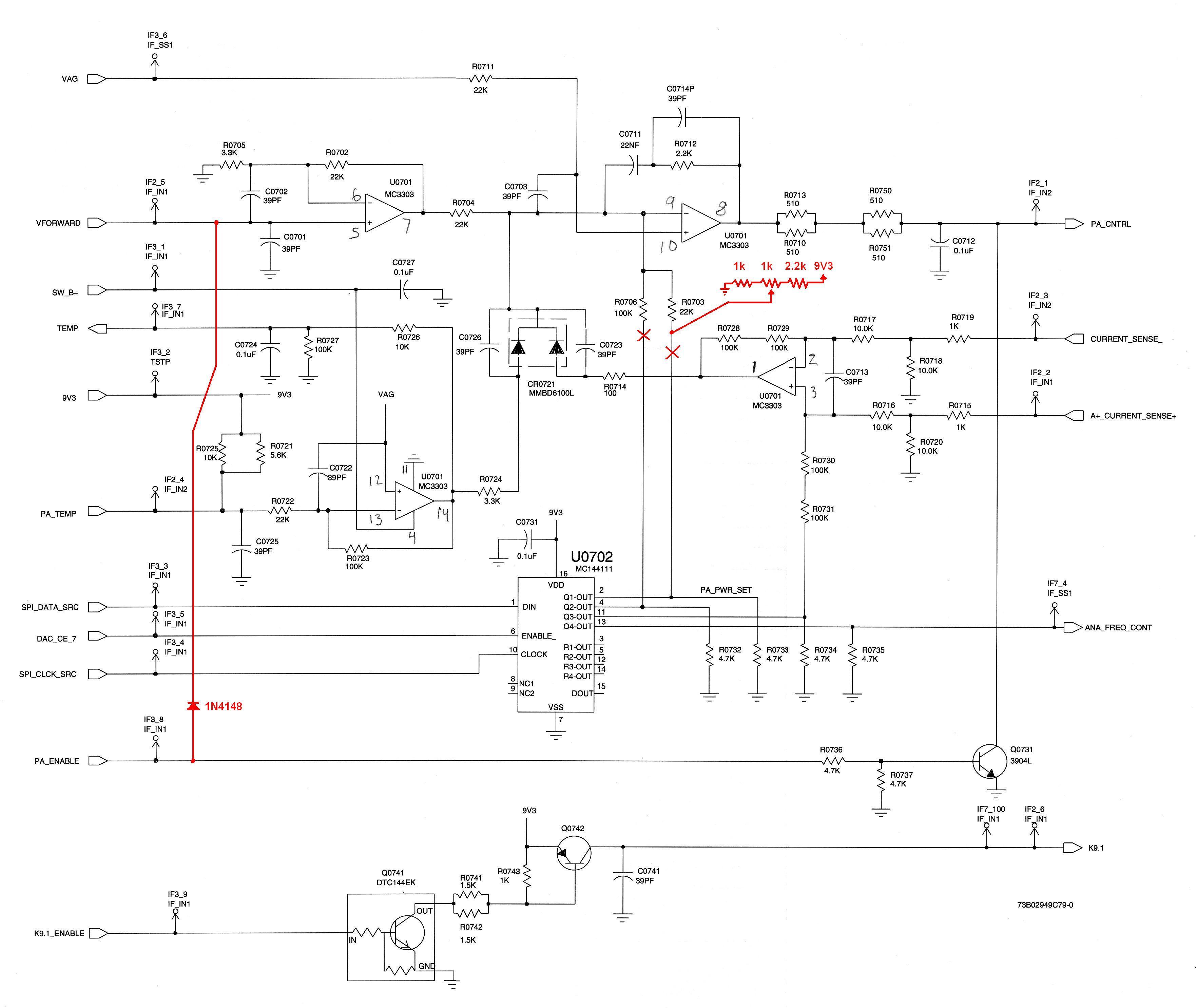
Many users of GTX 900 MHz radios for amateur repeaters are familiar with the inconsistent output power issue. After completing a full board replacement and adjusting deviation and output power, the radio performs well on test frequencies ranging from...
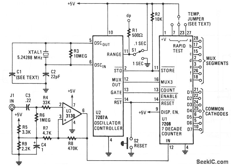
The circuit comprises an ICM7208 seven-decade counter (U1), an ICM7207A oscillator controller (U2), and a CA3130 biFET operational amplifier (U3). IC U1 counts input signals, decodes them into a 7-segment format, and outputs signals that drive a 7-digit display....
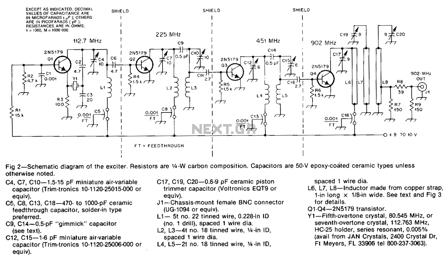
The oscillator, Q1, is a standard overtone circuit. A fifth-overtone crystal, 80.545 MHz, is operated on the seventh overtone, 112.763 MHz. C6 couples the output of the oscillator to Q2, which operates as a doubler to 225.5 MHz. A...
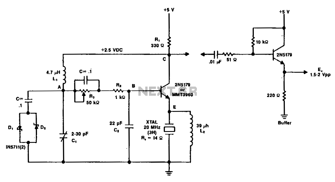
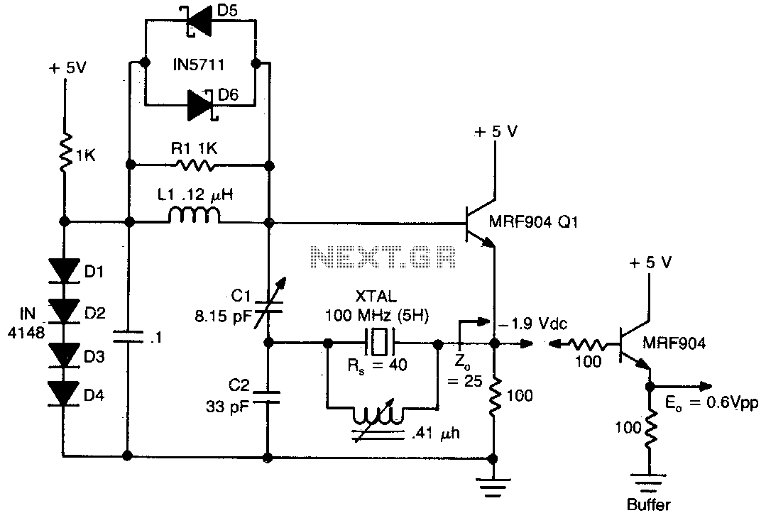
A typical circuit operating at 20 MHz is illustrated. The crystal, featuring an internal series resistance (Rs) of 14 ohms, oscillates at its third harmonic frequency. Diode clamps D1 and D2 ensure constant amplitude control. The transistor functions continuously...