
Fan Controller with PIC12F675

This circuit functions as a variable speed controller specifically designed for automotive heater blower motors, utilizing a compact and efficient design. The system operates on a 12-volt supply, drawing power directly from the vehicle's existing electrical system, which simplifies installation through a two-wire connection. The central processing unit, a PIC12F675 microcontroller, is programmed to interpret the position of a 10kΩ linear potentiometer. This potentiometer allows the user to adjust the blower speed, effectively modulating the output through pulse-width modulation (PWM).
In operation, the microcontroller generates PWM signals that control a DC motor driving the fan. The duty cycle of these signals can vary from 0% to 98%, allowing for precise control over the fan speed. At the lowest setting, the PWM output is effectively turned off, cutting power to the motor entirely. This feature is crucial for energy efficiency and user control.
The circuit includes a diode and a 100µF capacitor, which work in tandem to ensure that the voltage remains at a stable 12 volts during operation, even under varying loads. This is important for maintaining consistent performance of the blower motor. The LM78L05 voltage regulator supplies the necessary 5 volts for the PIC microcontroller, ensuring reliable operation of the control logic.
The IRL7833 MOSFET is utilized as the switching element in this design, chosen for its low on-resistance of 0.004 ohms, which minimizes power losses and heat generation. With a current handling capacity of up to 10 amps, the device is suitable for a wide range of applications beyond just heater blowers. A small heatsink is recommended to dissipate any heat generated during operation, particularly at higher loads.
The layout of the circuit is optimized for current handling, with careful attention given to the placement of the FET and its connections to the terminals. This enhances performance and reliability, particularly in automotive environments where vibrations and temperature fluctuations can affect electronic components.
Additionally, the design incorporates a watchdog timer function within the PIC microcontroller, which is essential for maintaining system stability. Given that the device is frequently powered on and off by the vehicle's ignition and blower switch, the watchdog timer provides necessary hardware resets, preventing potential system hangs or failures.
This circuit design represents a robust solution for controlling the speed of automotive heater blowers, balancing efficiency, reliability, and user control.This device acts as a variable speed control for the heater blower in a car. It takes its power directly from the existing wiring and connects with just 2 wires. It will also work for any 12 volt device up to 10 amps. A PIC12F675 provides all of the necessary functions. It reads the (10k) linear potentiometer and generates appropriately timed pulses to control the DC motor running the fan. The extreme low position cuts the power entirely. The circuit is relatively simple. The wire to the blower motor (either high or low side) is cut and connection is made to the circuit with the more positive side at the top connection.
The diode and 100uf capacitor always provide full 12 volts because the Pulse Width Modulation scheme always provides a minimum 'off' time of the power cycle. The LM78L05 (note unusual pinouts) provides 5 volts for the PIC. Depending on the setting of the 10k pot, GP5 sends out positive pulses with duty cycles between 0 and 98 percent.
The IRL7833 has a rated 'on' resistance of 0.004 ohms, so it can handle about 10 amps with just a small heatsink. The layout was done so as to maximize the current handling between the FET and the terminals (upper left area).
When printing the layout, the arrow should measure exactly 2 inches. Here are the Source and Hex files. Note the use of the watchdog timer function. Since this device is constantly powered on and off by the ignition and main blower switches, this provides hardware resets when needed. 🔗 External reference
Related Circuits
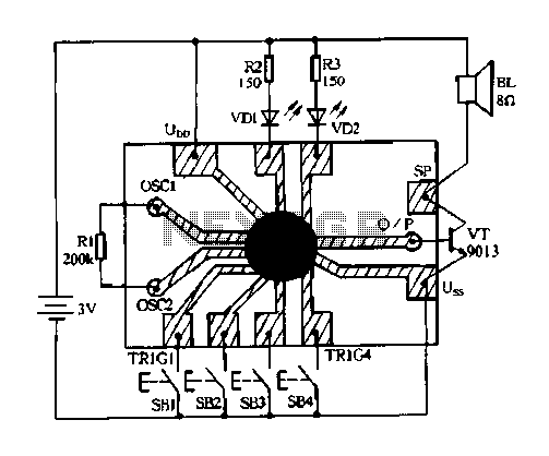
Constantly changing light and sound analog controller circuit 04 The circuit designated as the "Constantly Changing Light and Sound Analog Controller Circuit 04" is designed to modulate both light and sound outputs in a dynamic manner. This type of...
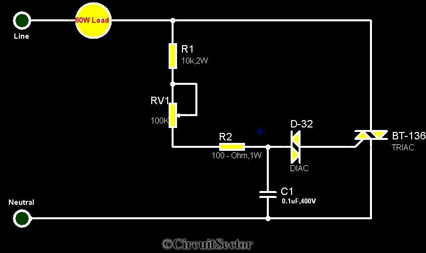
The circuit diagram presented is a triac-diac electronic fan regulator designed to reduce power consumption of electric fans, even at low speeds. Traditional resistor-inductor fan regulators tend to generate excess heat, wasting energy when the fan operates at lower...
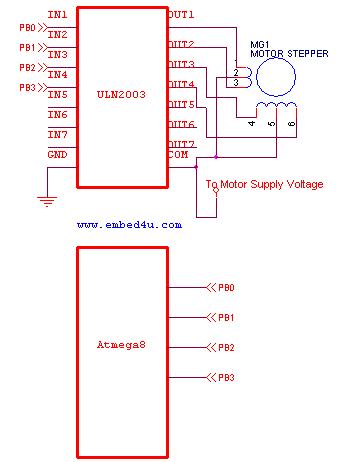
This tutorial utilizes the ATmega8 microcontroller with a 4 MHz crystal oscillator and unipolar stepper motors. The ULN2003, a Darlington pair driver integrated circuit, is employed for motor control. The ATmega8 microcontroller is a versatile 8-bit device from the AVR...
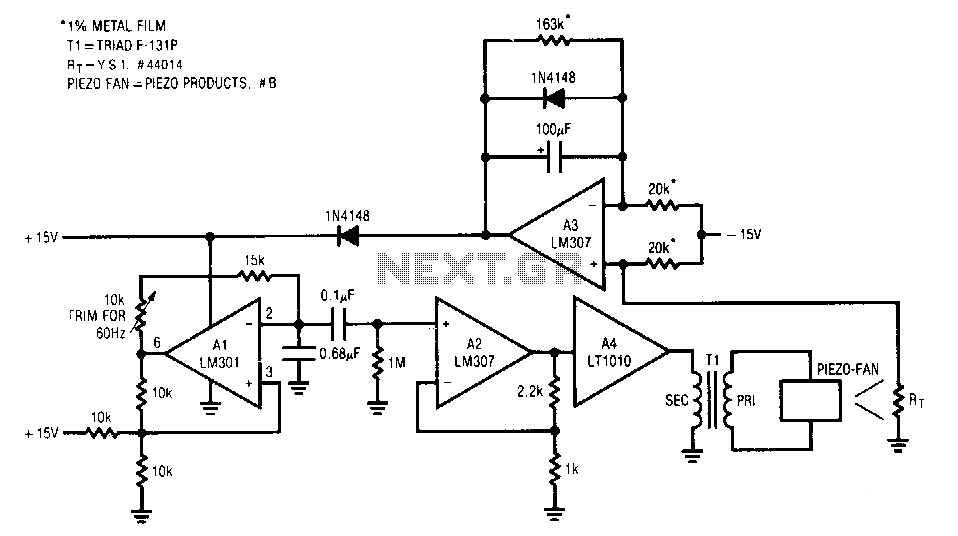
The fan used is a new electrostatic type, known for its reliability due to the absence of wearing parts. These devices require a high-voltage drive. When power is applied, the thermistor located in the fan's exhaust stream has a...
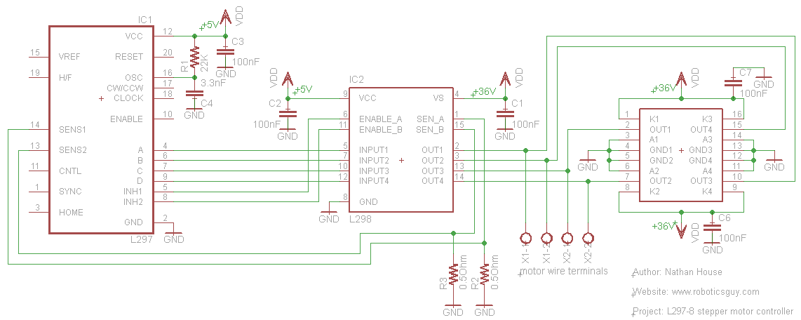
An efficient method for constructing a stepper motor controller involves creating a printed circuit board (PCB) and then placing the components onto it. Once the PCB is fabricated, the assembly and soldering of components is a quick process, especially...
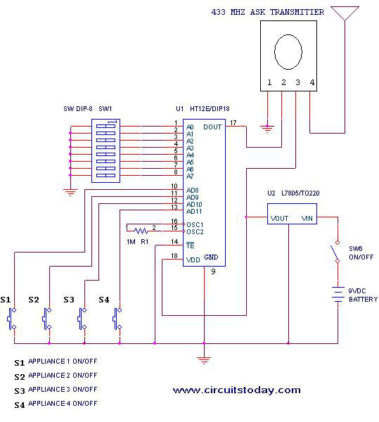
This project outlines a simple remote control system utilizing RF communication without the use of a microcontroller. The remote is designed for various home appliances such as televisions, fans, and lights, providing significant convenience by allowing operation from a...